

Head mounted device and head mounted system
a head mounted device and head mounted technology, applied in the direction of headwear caps, hats, protective garments, etc., can solve the problems of inconvenience to the wearing person and inability to confirm
- Summary
- Abstract
- Description
- Claims
- Application Information
AI Technical Summary
Benefits of technology
Problems solved by technology
Method used
Image

Examples
first embodiment
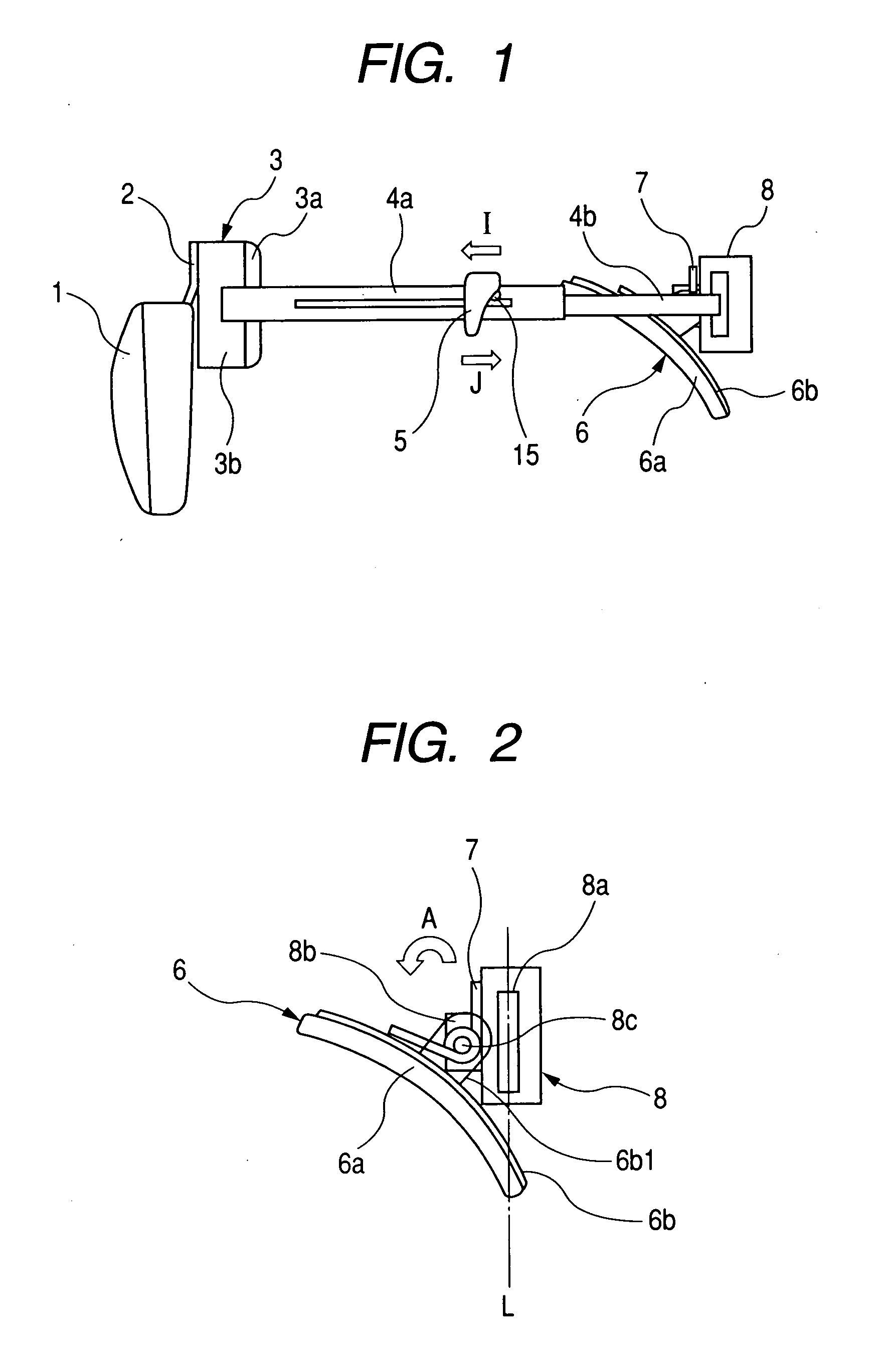
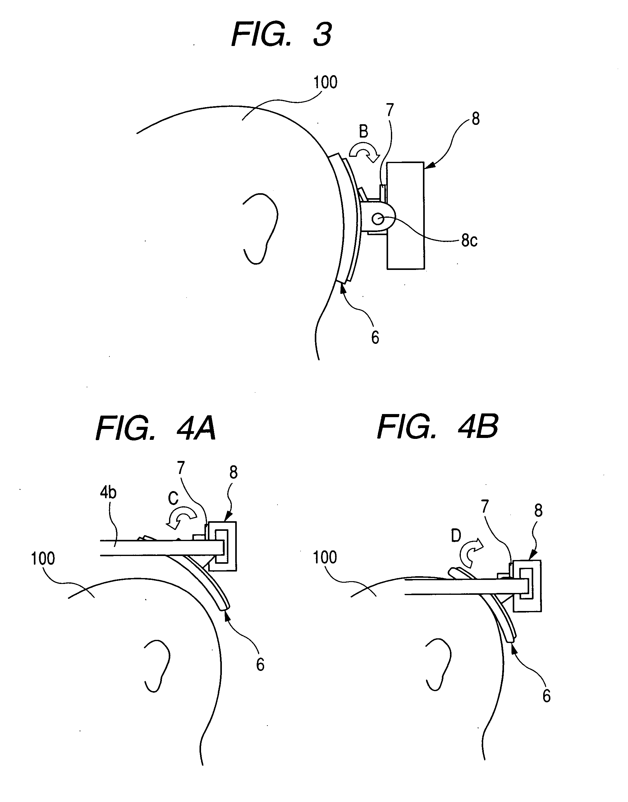
[0032]FIG. 1 is a side view of a head mounted system (HMD) which is a first embodiment of the present invention. FIG. 2 is a side view of a back head pressing portion (head holding portion), and FIG. 3 is a side view of the back head pressing portion in a mounted state. FIG. 4A and FIG. 4B are views showing the movement of the back head pressing portion in a process of mounting the HMD.
[0033] A front head pressing portion 3 is provided with a front head pad mounting base 3b formed in a shape conforming to a shape of the front head of a wearing person wearing the HMD; and a front head pressing pad 3a mounted onto the front head pad mounting base 3b. The front head pressing pad 3a abuts on a front head of the wearing person when the HMD is mounted.
[0034] A back head pressing portion 6 is provided with a back head pad mounting base 6b formed in a shape conforming to a shape of the back head of the wearing person wearing the HMD and a back head pressing pad 6a mounted onto the back he...
second embodiment
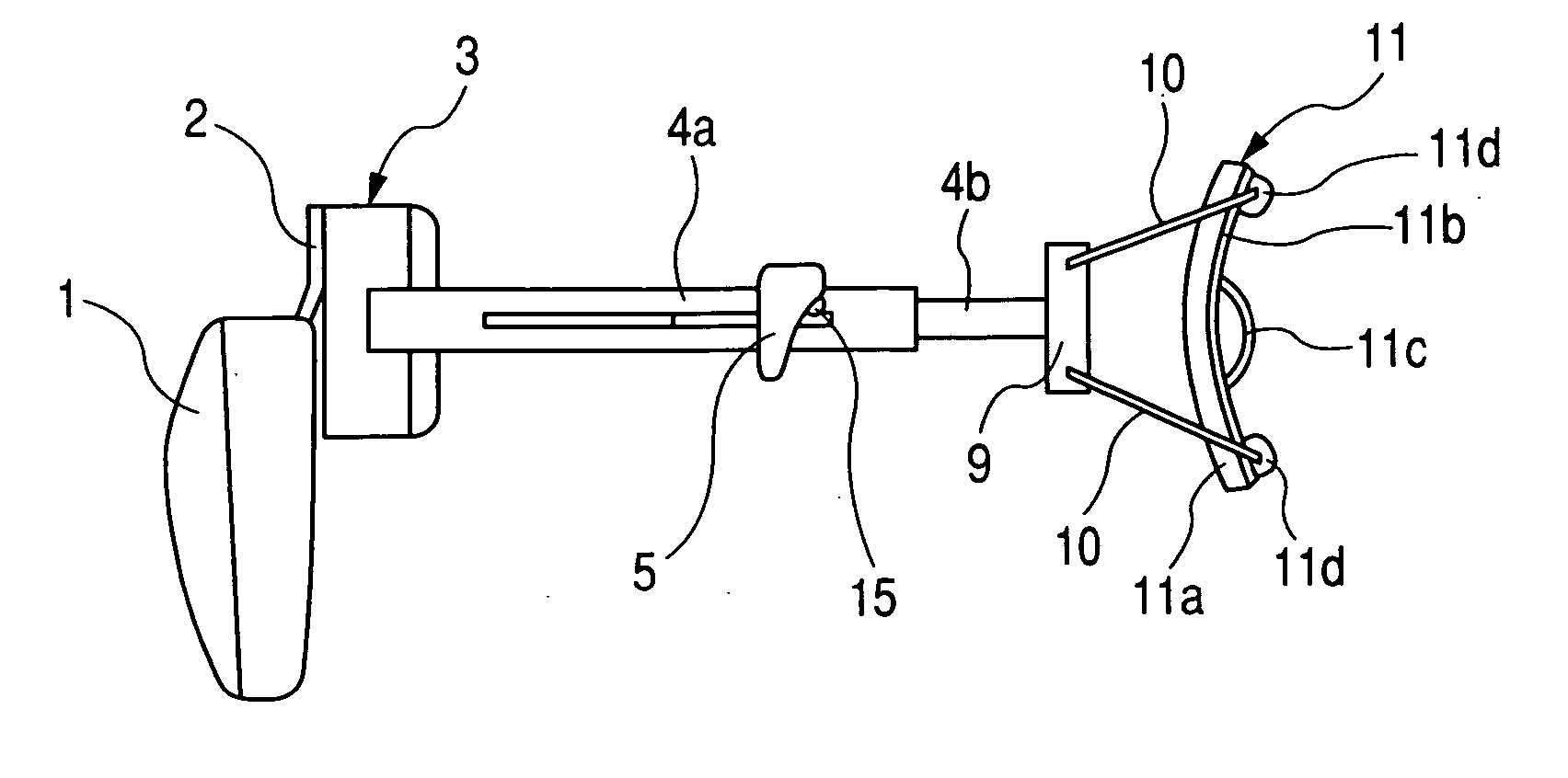
[0050]FIG. 5 is a side view of the head mounted display (HMD) which is a second embodiment of the present invention, FIG. 6 is a side view of the back head pressing portion (head holding portion), and FIG. 7 is a side view showing a part of the HMD in the mounted state. In these drawings, the like numerals and symbols are used for the members which are the same as the members of the first embodiment, and the explanation thereof is omitted.
[0051] A back head pressing portion 11 is provided with a back head pad mounting base 11b and a back head pressing pad 11a mounted onto the back head pad mounting base 11b. The back head pressing pad 11b is made of a deformable material.
[0052] In addition, the back head pressing portion 11 has a leaf spring 11c. When the HMD is in a state (non-mounted state) as shown in FIG. 5, the leaf spring 11c is protruded in a convex shape toward a direction opposite to the side of the back head pressing pad 11a. The back head pressing portion 11 (the back h...
third embodiment
[0060]FIG. 8 is a side view of the head mounted display (HMD) according to a third embodiment of the present invention, FIG. 9 is a side view of the back head pressing portion (head holding portion), and FIG. 10 is a side view of the back head pressing portion in the mounted state. In these drawings, the same numerals and symbols are used for the members which are the same as the members of the first embodiment, and the explanation thereof is omitted.
[0061] A back head pressing portion 12 is provided with: a back head pressing pad (a first pad) 12a abutting the back head of the wearing person when being mounted; and a back head pad mounting base (a supporting member) 12b to which the back head pressing pad 12a is mounted. In addition, a top head supporting portion 13 is provided with: a top head pressing pad (a second pad) 13a abutting on the top head of the wearing person when being mounted; and a top head pad mounting base (a supporting member) 13b to which the top head pressing ...
PUM
 Abstract
Description
Claims
Application Information