Variable capacity type orbiting vane compressor

a vane compressor and variable capacity technology, applied in the field of orbiting vane compressors, can solve the problems of difficult variation, limited volume ratio change, and difficult to vary the capacity and achieve the effect of easy and convenient volume change and capacity change of the orbiting vane compressor

Inactive Publication Date: 2006-04-06
LG ELECTRONICS INC
View PDF10 Cites 1 Cited by
  • Summary
  • Abstract
  • Description
  • Claims
  • Application Information

AI Technical Summary

Benefits of technology

[0022] Therefore, the present invention has been made in view of the above problems, and it is an object of the present invention to provide a variable capacity type orbiting vane compressor that is capable of more easily changing a ratio in volume of an inner compression chamber to an outer compression chamber, the inner and outer compression chambers being formed in a cylinder through an orbiting movement of an orbiting vane, whereby capacity of the orbiting vane compressor is easily and conveniently changed, and therefore, the orbiting vane compressor is operated with various capacities.

Problems solved by technology

However, it is very difficult to vary the ratio in volume of the inner compression chamber A2 to the outer compression chamber B2 by either changing the thickness of the circular vane 51 or changing the diameter of the annular space 42, and therefore, change of the volume ratio is performed with limits.
In conclusion, it is not easy to vary the capacity of the orbiting vane compressor.

Method used


Image

  • Variable capacity type orbiting vane compressor
  • Variable capacity type orbiting vane compressor
  • Variable capacity type orbiting vane compressor

Examples


first embodiment

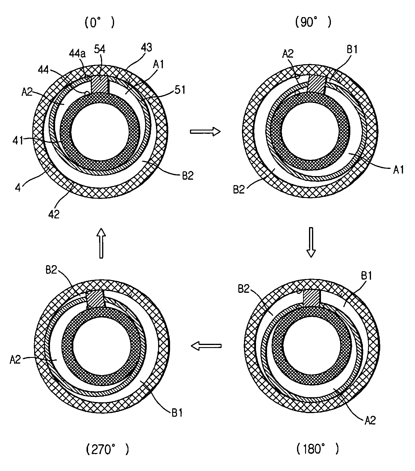
[0048] In the illustrated first embodiment of the present invention, the thickness of the vane plate 50 inside the circular vane 51 is increased, and the length of an inner ring 41 disposed at the upper part of the cylinder 4 is decreased as much as the increased thickness of the vane plate 50, so as to reduce the volume of an inner compression chamber A2 formed between the inner ring 41 of the cylinder 4 and the circular vane 51. As a result, a ratio in volume of the inner compression chamber A2 to an outer compression chamber B2 of the circular vane 51 is changed, and therefore, total capacity of the orbiting vane compressor is changed.

[0049] A more detailed description will be given of the change of the ratio in volume of the inner compression chamber A2 to the outer compression chamber B2 of the circular vane 51 with reference to FIG. 5. In the conventional orbiting vane compressor, the height of the vane plate 50 inside the circular vane 51 is the same as that of the van plate ...

second embodiment

[0054] In the illustrated second embodiment of the present invention, the thickness of the vane plate 50 inside the circular vane 51 between the circular vane 51 and the top boss 55a is increased, and the length of the inner ring 41 disposed at the upper part of the cylinder 4 is decreased as much as the increased thickness of the vane plate 50, so as to reduce the volume of the inner compression chamber A2 formed between the inner ring 41 of the cylinder 4 and the circular vane 51. As a result, a ratio in volume of the inner compression chamber A2 to an outer compression chamber B2 of the circular vane 51 is changed, and therefore, total capacity of the orbiting vane compressor is changed.

[0055] A more detailed description will be given of the change of the ratio in volume of the inner compression chamber A2 to the outer compression chamber B2 of the circular vane 51 with reference to FIG. 7. In the conventional orbiting vane compressor, the height of the vane plate 50 inside the c...


PUM


Abstract

Disclosed herein is a variable capacity type orbiting vane compressor that is capable of more easily changing a ratio in volume of an inner compression chamber to an outer compression chamber, the inner and outer compression chambers being formed in a cylinder through an orbiting movement of an orbiting vane, whereby capacity of the orbiting vane compressor is easily and conveniently changed. The thickness of a vane plate at any one of the inside and the outside of a circular vane formed at the upper part of the orbiting vane is larger than that of the vane plate at the other of the inside and the outside of the circular vane to change a ratio in volume of the inner compression chamber to the outer compression chamber in the cylinder.

Description

BACKGROUND OF THE INVENTION [0001] 1. Field of the Invention [0002] The present invention relates to an orbiting vane compressor, and, more particularly, to a variable capacity type orbiting vane compressor that is capable of more easily changing a ratio in volume of an inner compression chamber to an outer compression chamber, the inner and outer compression chambers being formed in a cylinder through an orbiting movement of an orbiting vane, whereby capacity of the orbiting vane compressor is easily and conveniently changed, and therefore, the orbiting vane compressor is operated with various capacities. [0003] 2. Description of the Related Art [0004] Referring to FIG. 1, there is illustrated a conventional hermetically sealed type orbiting vane compressor. As shown in FIG. 1, a drive unit D and a compression unit P are mounted in a shell 1 while the drive unit D and the compression unit P are hermetically sealed. The drive unit D and the compression unit P are connected to each o...

Claims


Application Information

Patent Timeline
Patent Type & Authority Applications(United States)
IPC IPC(8): F01C20/18F03C4/00F16N13/20F01C1/02
CPCF04C18/04F04C23/001F04C28/18F04C18/02F04C18/344F04C18/356
Inventor YOO, DONG-WONLEE, HYEONG-KOOKHWANG, SEON-WOONG
Owner LG ELECTRONICS INC
Why Eureka
Try Eureka