Combination equipment selection system using network

a technology of equipment selection and network, applied in the field of combined equipment selection system, can solve the problems of prolonged time until the user, host computer cannot securely obtain user information, and the workload on the host computer side becomes heavy, so as to achieve the effect of not exceedingly heavy workload and not prolonging the required time until the result is obtained

Inactive Publication Date: 2006-04-06
SANYO DENKI CO LTD
View PDF9 Cites 25 Cited by
  • Summary
  • Abstract
  • Description
  • Claims
  • Application Information

AI Technical Summary

Benefits of technology

[0011] In the system according to the present invention, the selection operation is carried out on the user terminal device. Therefore, even when the number of users increases, the workload on the host computer side will not become extremely heavy, and the required time until the result is obtained will not be prolonged. In the present invention, in order to enable the selection information to be displayed onto the display section of the user terminal device, a display permission must be obtained by transmitting the user information and selection information to the host computer. Consequently, each time the user is allowed to display the selection information onto the display section, the system can securely obtain the information from the user.

Problems solved by technology

With the arrangement according to the former technology, as the number of users increases, the workload on the host computer side becomes heavier, which lead to prolonged time until the user obtains the result.
With the arrangement according to the latter technology, since the user can confirm the cost estimation without transmitting the estimation result to the host computer, there is a problem that the host computer cannot securely obtain the user information.
In addition, with the latter technology, there is another problem that variable data are not provided to the user.

Method used


Image

  • Combination equipment selection system using network
  • Combination equipment selection system using network
  • Combination equipment selection system using network

Examples


Embodiment Construction

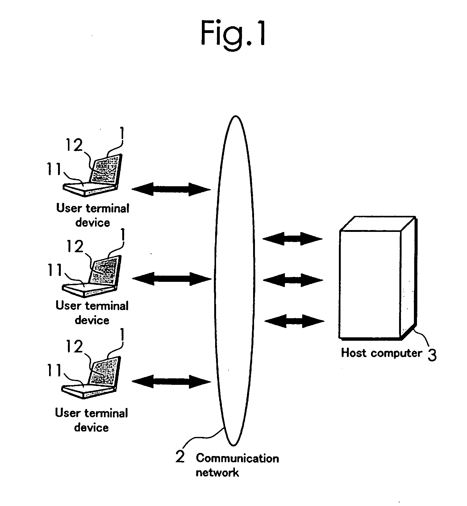
[0027] Now, some embodiments of the present invention will be described in detail with reference to the accompanying drawings. FIG. 1 shows an outline of a combined equipment selection system according to the present invention. This combined equipment selection system comprises a plurality of user terminal devices 1 each having an operation section 11 and a display section 12 and connected to a communication network and a host computer 3 connected to the communication network 2 for communicating with the plurality of user terminal devices 1 and obtaining user information from the user terminal devices 1. The user terminal device 1 is typically a personal computer, and a specified program is installed on that computer. The communication network 2 is a so-called global communication network such as the Internet. The host computer 3 is managed by a person or a company which is operating this system.

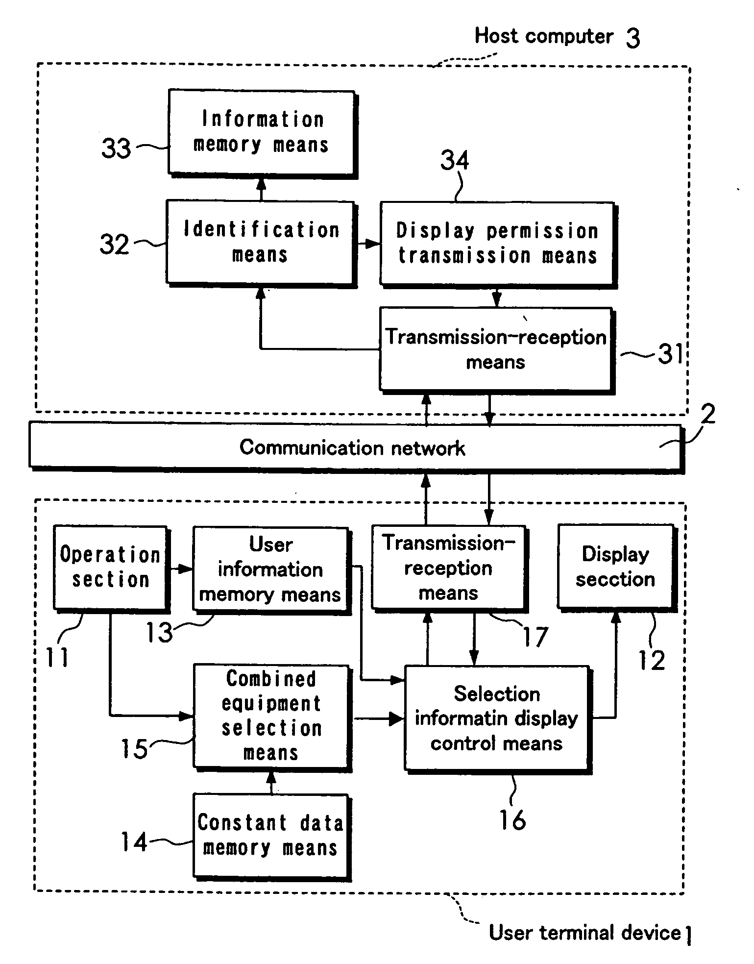
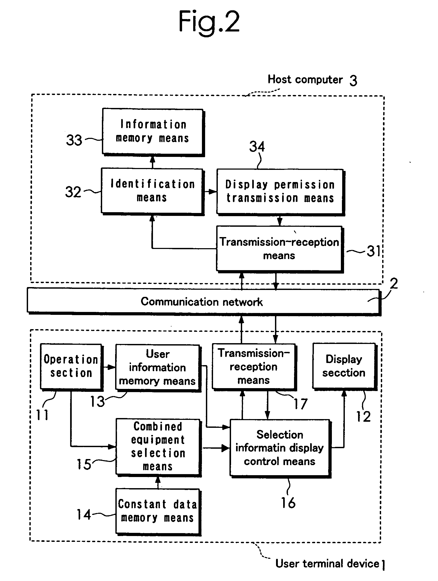
[0028]FIG. 2 is a block diagram showing a configuration of an embodiment of the present...


PUM


Abstract

The present invention provides a combined equipment selection system which is capable of reducing the load on the host computer and securely obtaining the user information. A user terminal device 1 comprises a user information memory means 13 for storing the user information, a constant data memory means 14 for storing constant data, a combined equipment selection means 15 and a selection information display control means 16. The combined equipment selection means 15 carries out a selection operation which selects one or more other combined equipment different from the service equipment and suitable for being combined with a service equipment, based on the model information and operational conditions of the service equipment as well as the constant data stored in the constant data memory means. The selection information display control means 16 requests a display permission from the host computer 3 for displaying the selection information onto the display section on condition that the user information and selection information are transmitted to the host computer 3, and displays the selection information onto the display section 12 only when the display permission is obtained from the host computer 3.

Description

TECHNICAL FIELD [0001] The present invention relates to a combined equipment selection system using a communication network, for selecting an equipment which can be combined with another equipment a user wishes to use. BACKGROUND ART [0002] The combination and specification of various equipments have been conventionally determined by a computer system using a communication network. For example, the Japanese Patent Application Laid-open Publication No. 24562 / 2000 discloses a technology by which a host computer performs operations and transmits the result to a user terminal device when a specification is determined between a registered user and a supplier or dealer. The Japanese Patent Application Laid-open Publication no. 41875 / 2000 discloses a technology by which a host computer obtains user information by allowing a user to carry out cost estimation of order-made house building at a user terminal device using a pre-distributed program and to transmit the estimation to the host comp...

Claims


Application Information

Patent Timeline
Patent Type & Authority Applications(United States)
IPC IPC(8): G06F15/16G05B23/02H04L29/08
CPCG06Q10/087G06Q10/10H04L67/10G06F17/00G06F15/16H04L12/28
Inventor KANAYAMA, MASATOSHIKATOU, AKIRAISHIZEKI, NOBURU
Owner SANYO DENKI CO LTD
Why Eureka
Try Eureka