
Spray can holding and actuating device

a technology of actuating device and spray can, which is applied in the directions of packaging, liquid dispensing, transportation and packaging, etc., can solve the problems of user inconvenience, stability and security of spray can attachment, and the above-described prior art device is somewhat complex and expensive to manufacture, and achieves the effect of simple and economical manufacturing

Inactive Publication Date: 2006-04-13
DELSHAR INDS
View PDF25 Cites 2 Cited by
  • Summary
  • Abstract
  • Description
  • Claims
  • Application Information

AI Technical Summary

Benefits of technology

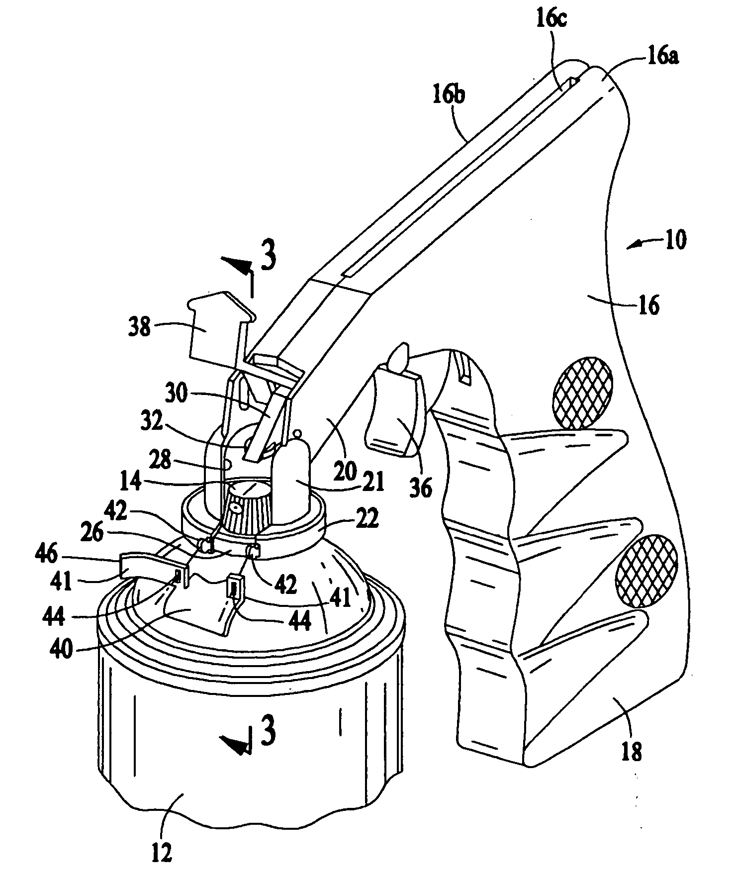
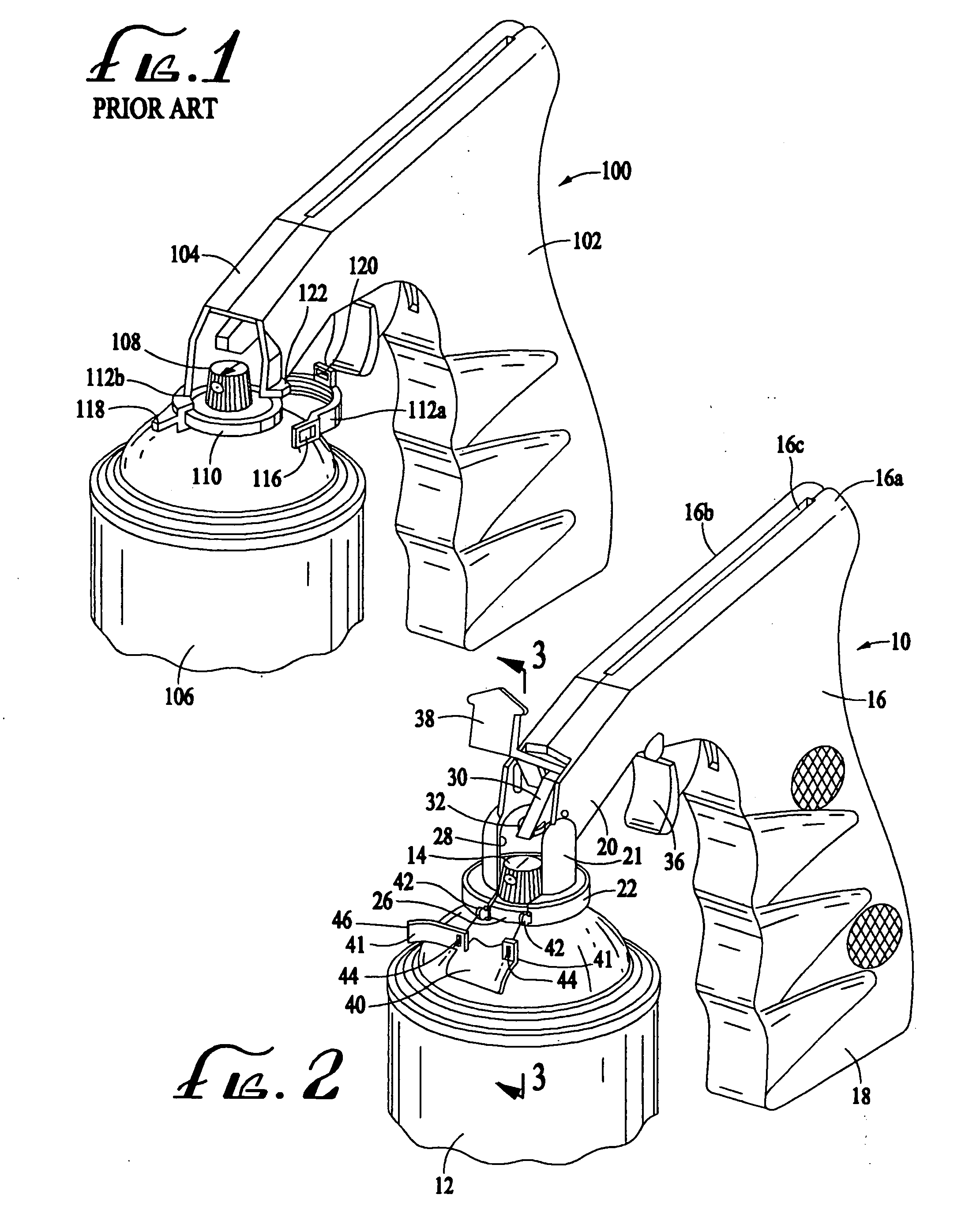
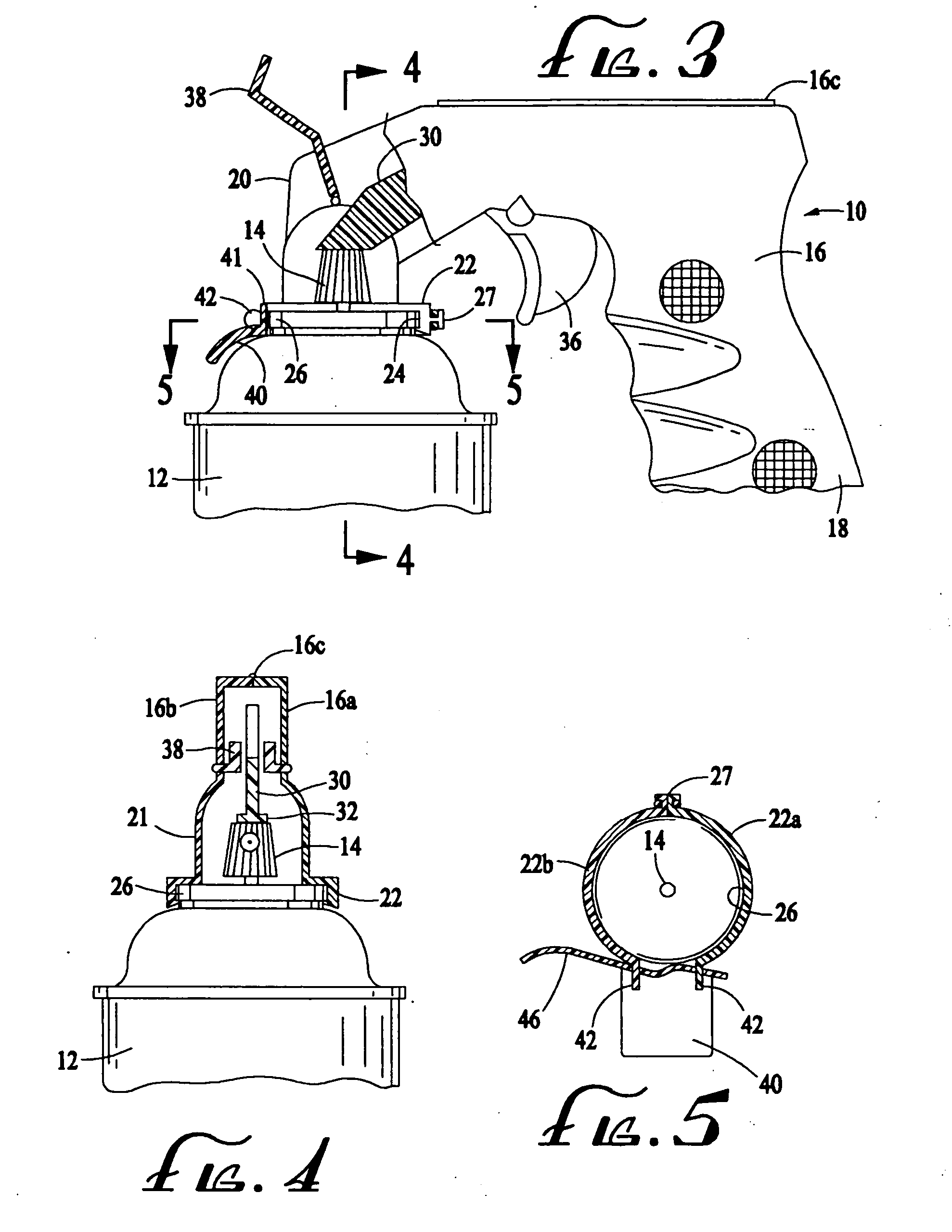
[0018] As will be more fully appreciated from the detailed description below, all of the embodiments of the present invention provide secure attachment of the spray can holding and actuation device to a spray can, even if the can is quite heavy. Moreover, these embodiments can be simply and economically manufactured using conventional injection molding techniques, and thus can easily be incorporated into existing spray can holding and actuation devices.

Problems solved by technology

The above-described prior art device has proved somewhat complex and expensive to manufacture, and there remain some problems with the stability and security of the can attachment, especially with larger and heavier cans.
Furthermore, some users find it cumbersome to line up the slotted tab 120 so that it receives the projection 122.

Method used


Image

  • Spray can holding and actuating device
  • Spray can holding and actuating device
  • Spray can holding and actuating device

Examples


first embodiment

[0045] The latch 60 is pivotable between an open or unlocked position and a closed or locked position. In the unlocked position (shown in solid outline in FIG. 8), the second end of the latch is clear of the second collar segment 54b. In the locked position (shown in FIG. 6 and in phantom outline in FIG. 8), the tongue or bead 64 on the second end of the latch 60 is fully inserted into the channel 59 in the second collar segment 54b, and is frictionally engaged therein, whereby the latch 60 becomes securely engaged with the second collar segment 54b. In this locked position, the curved inner surface 61 of the latch 60 is brought to bear against the front portion of the rim 26, thereby forming a tight-fitting rim engagement structure in combination with the collar 52. In addition, the attachment of the pivot pin 62 in the socket 58 is such that the movement of the latch 60 toward its locked position advantageously urges the flexible portion 57 of the first collar segment 54a toward t...

fourth embodiment

[0047] A can holding and actuation device 10″ in accordance with a fourth embodiment is illustrated in FIGS. 11-13. In this embodiment, a substantially annular collar 22″ is formed by two collar segments 22a″ and 22b″ joined at a rear juncture 27″. The collar 22″ is open at the front, with two opposed ends separated by a gap. The device 10″ has a front portion 20″ that terminates in a shroud 80 that has an opening 28′ at the front to permit the dispensing of the can's contents from the nozzle in the pushbutton 14. The opening 28′ of the shroud 80 is approximately equal in width to the gap at the front of the collar 22″. The shroud 80, like the body of the device 10″ of which it is an integral part, is bifurcated so that each of its halves is integral with one of the body halves 16a, 16b, and is joined at its bottom end to the collar 22″. Thus, one shroud half is integral with the first collar segment 22a″, and the other shroud half is integral with the second collar segment 22b″.

[0...


PUM


Abstract

A spray can holding and actuation device comprises a rim engagement element and a locking mechanism for compressing the rim engagement element against the rim surrounding the push-button valve on the can. The rim engagement element includes a compressible collar that is joined to a shroud that depends downwardly from a front portion of the device. The collar is dimensioned to fit around the rim, and it has a pair of opposed ends separated by a gap. In one embodiment, the locking mechanism includes a locking element that is attachable to the opposed collar ends when the ends are urged together to compress the collar against the rim. In another embodiment, the locking mechanism includes a latch that is pivotably attached to one of the collar ends and that is pivotable to a position in which it engages the other collar end and rim, whereby the collar ends are urged together to compress the collar against the rim. In still another embodiment, the shroud has a pair of opposed side surfaces, each of which is formed with an arcuate groove. A camming surface is formed in each of the grooves. The locking mechanism includes a latch that is pivotably attached to the rear surface of the shroud, and that has a pair of opposed arms, each of which terminates in a finger that rides in one of the grooves. The latch is pivotable between a first position in which the fingers are out of engagement with the camming surfaces, and a second position in which the fingers engage the camming surfaces. When the fingers engage the camming surfaces, the collar is compressed against the rim.

Description

CROSS REFERENCE TO RELATED APPLICATION [0001] Not Applicable FEDERALLY SPONSORED RESEARCH OR DEVELOPMENT [0002] Not Applicable BACKGROUND OF THE INVENTION [0003] The present invention relates to a device for both holding a pressurized container, such as an aerosol spray can, and for actuating the valve of the container to dispense its pressurized contents. Specifically, the present invention relates to an improvement in the mechanism by means of which these devices are attachable to such containers. [0004] Spray can holding and actuation devices are well known in the art, as exemplified by the following U.S. Pat. No. 2,877,934—Wallace; U.S. Pat. No. 3,172,582—Belpedio; U.S. Pat. No. 3,189,232—Joffe, and, U.S. Pat. No. 4,089,440—Lee. Further examples of such devices are disclosed in the following United Kingdom patent specifications: 1,163,978; 1,343,881; 1,487,719; 2,001,706 (published application); and 2,038,952 (published application). [0005] One of the most popular types of spray...

Claims


Application Information

Patent Timeline
Patent Type & Authority Applications(United States)
IPC IPC(8): B65D83/14B65D83/16
CPCB65D83/202B65D83/22
Inventor BRODY, HARVEY
Owner DELSHAR INDS
Learn More