Microscope, detector, and method for microscopy

a microscope and detector technology, applied in the field of microscopes, can solve the problems of living specimens, much greater specimen damage, ultraviolet light illuminating, etc., and achieve the effect of simple and economical manufacture, uncomplicated and reliable determination

Inactive Publication Date: 2005-10-04
LEICA MICROSYSTEMS CMS GMBH
View PDF9 Cites 2 Cited by
  • Summary
  • Abstract
  • Description
  • Claims
  • Application Information

AI Technical Summary

Benefits of technology

[0013]It is therefore the object of the invention to describe a microscope that can be manufactured simply and economically and that permits uncomplicated and reliable determination, even during examination of the specimen, of the time-defined pulse width of the light pulses illuminating a specimen.
[0017]A further object of the invention is to describe a detector that can be manufactured simply and economically and that permits uncomplicated and reliable determination, even during examination of the specimen, of the time-defined pulse width of the light pulses illuminating a specimen.
[0023]The invention has the advantage of making possible, in simple and reliable fashion, a determination of the time-defined pulse width of the light pulses illuminating a specimen. The determination is preferably made in parasitic fashion during examination of the specimen, so that a manual or automatic optimization of the pulse width of the light pulses of the illuminating light can also easily be implemented. A control loop that optimizes the pulse width to a maximum fluorescent light yield is preferably provided for this purpose.

Problems solved by technology

The use of ultraviolet illuminating light has the disadvantage, especially for living specimens, of much greater specimen damage.
With cemented optical components in particular, such as lens element groups in a microscope objective, illumination with ultraviolet light causes irreversible damage to the cement and to the lens elements.
A further disadvantage of illumination with ultraviolet light has to do with the shallower penetration depth into biological specimens.
A parasitic measurement of the time-defined pulse widths of the exciting light during microscopic examination of a specimen is important, since the pulse widths of the pulses emitted by the laser may fluctuate greatly; this directly influences the nonlinear effects that are being deliberately excited in the specimen (two-photon absorption, generation of second harmonic, etc.), and can thus result in incorrect information in the image.
Parasitic monitoring of this kind with an autocorrelator is very complex and laborious.

Method used


Image

  • Microscope, detector, and method for microscopy
  • Microscope, detector, and method for microscopy
  • Microscope, detector, and method for microscopy

Examples


Embodiment Construction

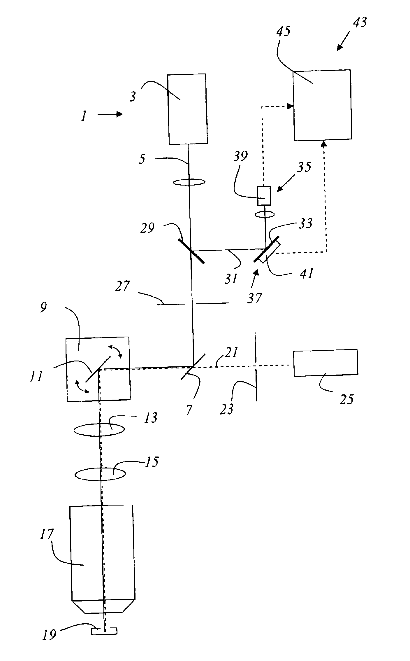
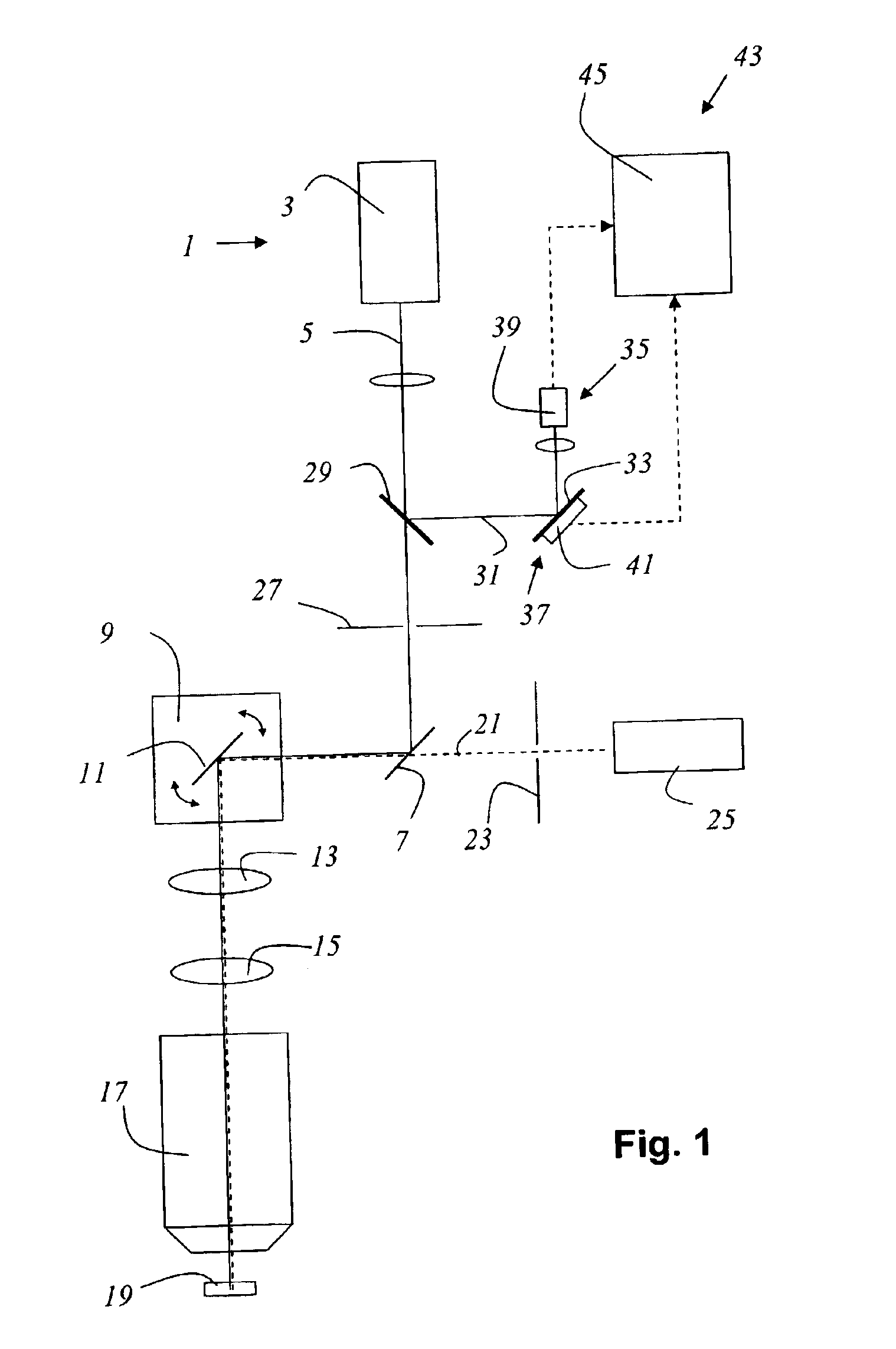
[0041]FIG. 1 schematically shows a microscope according to the present invention that is embodied as a confocal scanning microscope. The microscope contains a light source 1 that is embodied as a mode-coupled titanium:sapphire laser 3. Light 5 emitted from titanium:sapphire laser 3, which has a wavelength of 780 nm, contains light pulses with a repetition rate of 80 MHz. The duration of the light pulses is approx. 1 ps. After passing through an excitation pinhole 27, light 5 is reflected by a main beam splitter 7 of a beam deflection device 9 that contains a gimbal-mounted mirror 11, and is guided by beam deflection device 9, through scanning optical system 13, tube optical system 15, and objective 17, over or through specimen 19. Detected light 21 proceeding from specimen 19 travels along the same light path through beam deflection device 9 back to main beam splitter 7, passes through the latter, and after passing through detection pinhole 23 strikes photomultiplier 25. In the draw...


PUM


Abstract

A microscope having a light source that emits light pulses for illumination of a specimen, the light pulses containing photons having a photon energy, is disclosed. The microscope is characterized in that a detector, which has an energy band gap between a quiescent state and an active state that is greater than the photon energy, is provided for determination of a time-defined pulse width of the light pulses. Also described are a detector for determination of a time-defined pulse width of light pulses for illumination of a microscopic specimen, and a method for microscopy.

Description

CROSS REFERENCE TO RELATED APPLICATIONS[0001]This application claims priority of the German patent application 102 06 980.8 which is incorporated by reference herein.FIELD OF THE INVENTION[0002]The invention concerns a microscope having a light source that emits light pulses for illumination of a specimen, the light pulses containing photons having a photon energy.[0003]The invention furthermore concerns a detector for determining a time-defined pulse width of light pulses for illumination of a microscopic specimen.[0004]The invention additionally concerns a method for microscopy.BACKGROUND OF THE INVENTION[0005]For the examination of biological specimens, it has been usual for some time to prepare the specimen with optical markers, in particular with fluorescent dyes. Often, for example in the field of genetic investigations, several different fluorescent dyes are introduced into the specimen and become attached specifically to certain specimen constituents. From the fluorescence p...

Claims


Application Information

Patent Timeline
Patent Type & Authority Patents(United States)
IPC IPC(8): G02B21/00
CPCG02B21/002
Inventor MOELLMANN, KYRA
Owner LEICA MICROSYSTEMS CMS GMBH
Why Eureka
Try Eureka