Wire pulling assist device

a technology of assist device and wire, which is applied in the direction of cables, special-purpose vessels, transportation and packaging, etc., can solve the problems of metal clad wire running through the opening of the stud, most often a time-consuming annoyance, and no means to prevent mc wire, etc., to achieve effective and efficient address

Inactive Publication Date: 2013-12-05
DERCOLE ROBERT
View PDF4 Cites 3 Cited by
  • Summary
  • Abstract
  • Description
  • Claims
  • Application Information

AI Technical Summary

Benefits of technology

[0004]It is thus the object of the present invention to provide a wire pulling assist tool or device which effec...

Problems solved by technology

However, running metal clad wire through openings in studs, particularly metal studs, is most often a time consuming annoyance.
There is currently no means to pre...

Method used


Image

  • Wire pulling assist device
  • Wire pulling assist device
  • Wire pulling assist device

Examples


Embodiment Construction

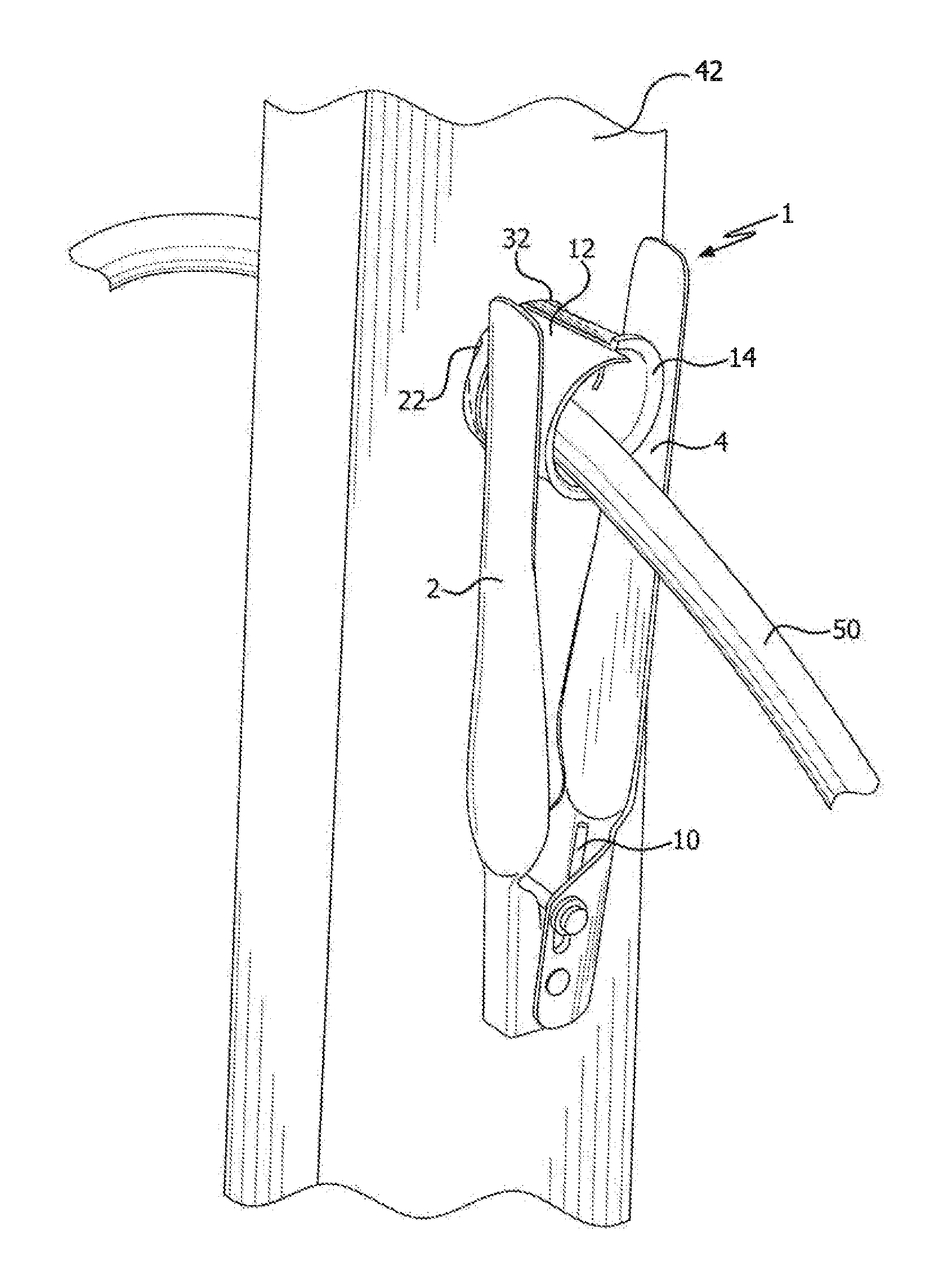
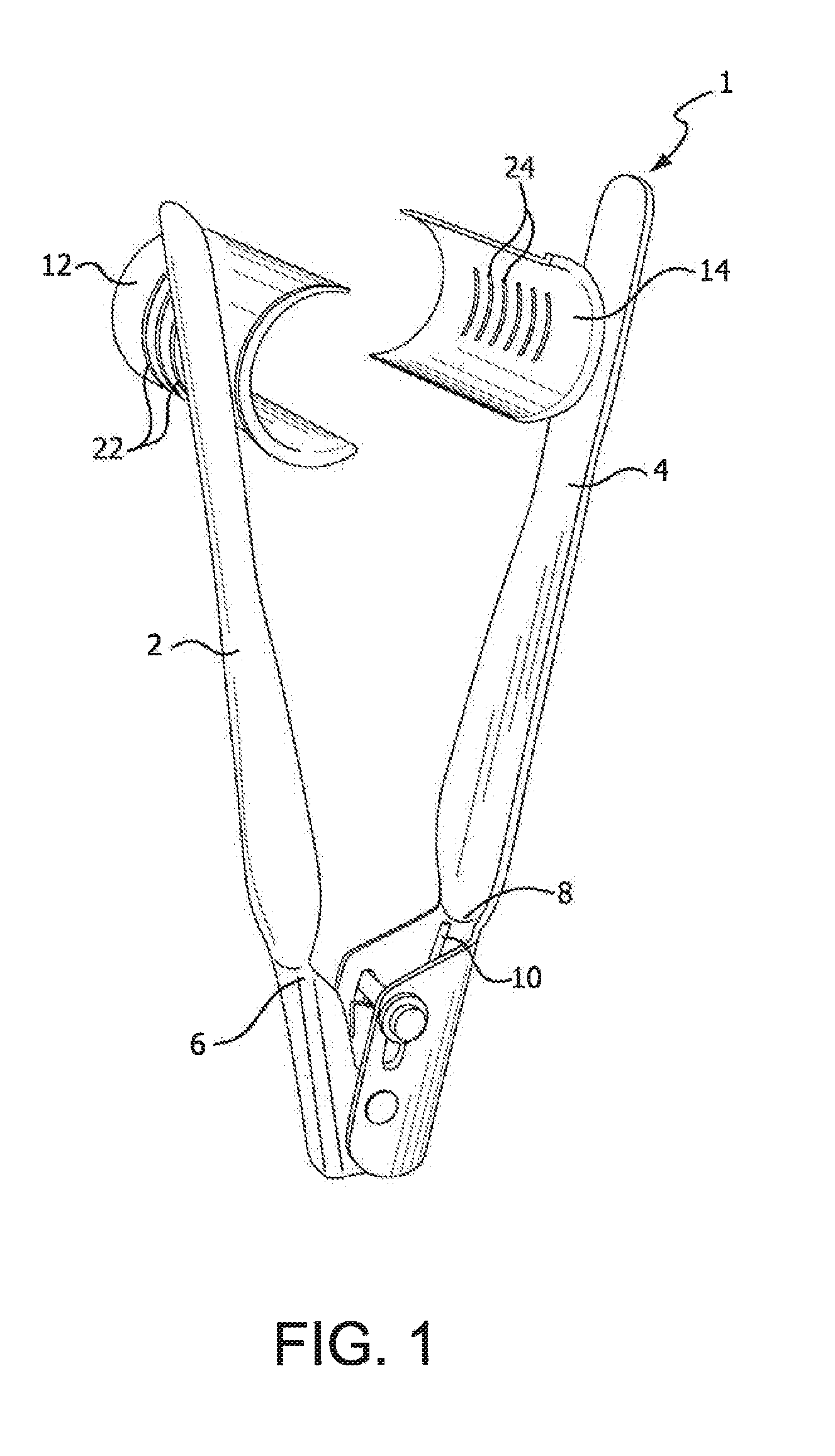
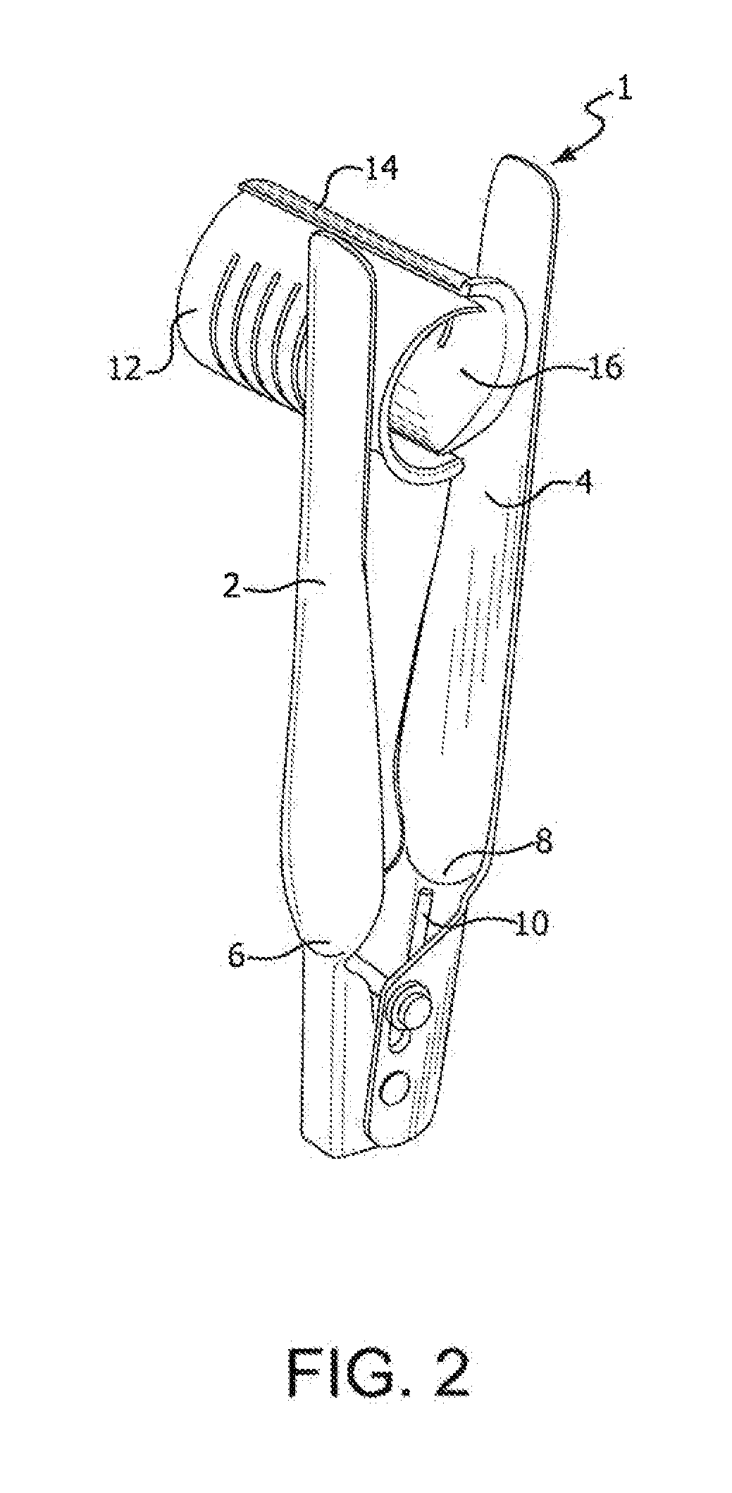
[0015]Wire pulling assist device 1 is a tong shaped tool having arm members 2 and 4 secured together at their respective lower ends 6 and 8. Leaf spring 10 is located in the space between lower ends 6 and 8 and is configured to biasedly maintain arm members 2 and 4 spread apart in an open, first position. See FIG. I. Application of manual pressure on arm members 2 and 4 will act against the biasing force of spring 10 and compel the arm members to rotate towards each other, to a closed, second position. See FIG. 2.

[0016]Wire supports 12 and 14 are attached to and extend from near the distal ends of arm members 2 and 4. Wire supports 12 and 14 consist of curved elements. When arm members 2 and 4 are pushed together, the end sections of wire supports 12 and 14 overlap each other in varying degrees. In this manner, it can be appreciated that the size of opening 16 formed between wire supports 12 and 14, when arm members 2 and 4 are compelled together, can be varied, depending on the amo...


PUM


Abstract

A wire pulling assist device has a tong shaped member having two arms biasedly connected at one of the two ends of each arm. A leaf spring at the connected ends of the arms maintains the device in a biasedly open position when the tool is not being used. Wire supports, consisting of curved elements, extend from near the second end of the arms. Applying a squeezing pressure on the arm members compels them and the wire supports towards each other, permitting the wire supports to be inserted into a hole in a metal stud. Metal clad wire can then be threaded through the wire supports and run smoothly and efficiently through the metal stud without impediment.

Description

BACKGROUND OF THE INVENTION[0001]Electricians, electrical contractors, and others in the construction trade are required, from time to time, to run electrical wire and cable through support studs. Pulling smooth electrical wire or cable through studs, including metal studs, presents little problem or extended effort. However, running metal clad wire through openings in studs, particularly metal studs, is most often a time consuming annoyance.[0002]Metal clad or MC wire comprises an outer covering of metal ridges. These ridges routinely get hung up on the sharp, thin edges of the metal stud openings through which they are pulled. This compels the electrician to stop the MC wire pulling process, walk over to the stud, dislodge the wire from the edge of the hole, and begin pulling again. The MC wire will inevitably hang up again and again, and the dislodging process will need to be repeated several times.[0003]There is currently no means to prevent MC wire from getting hung up on the e...

Claims


Application Information

Patent Timeline
IPC IPC(8): H02G1/06
CPCH02G1/06
Inventor D'ERCOLE, ROBERT
Owner DERCOLE ROBERT
Why Eureka
Try Eureka