Groove glazed window sash and fabrication method

Inactive Publication Date: 2005-04-21
ANDERSEN CORPORATION
View PDF35 Cites 40 Cited by
  • Summary
  • Abstract
  • Description
  • Claims
  • Application Information

AI Technical Summary

Benefits of technology

[0010] As the rails and stiles are pressed onto the edges of the glass unit, the glass slides between the foam-backed adhesive strips. Since the dual state adhesive is in its non-adhesive state as a result of application of the adhesive blocker, the glass slides easily across the adhesive, aided by the lubricating qualities of the blocker. Preferably, the width of the groove is selected so that the foam of the foam-backed strips is compressed by the advancing edge of the glass to between about zero and fifty percent (0-50%) of it uncompressed thickness. In this way, the adhesive layer is pressed firmly against the surface of the glass by the compression of the foam. The clamping jig then holds the rails and stiles in place for a predetermined length of time until the adhesive blocking agent dissipates and the dual state adhesive transitions to its second or adhesive state. This transition causes the adhesive to adhere to and form a continuous water tight seal against the surface of the glass around the entire periphery of the glass. The clamping jig is then retracted and the finished groove glazed window sash can be removed for incorporation into a window unit.
[0011] Th

Problems solved by technology

While prior groove glazed sashes and methods of fabricating them have been successful, there nevertheless have been inherent problems and shortcomings.
For example, the fabrication of groove glazed sashes generally has been a somewhat inefficient multi-step process involving partial assembly of the rails and stiles, mounting of the glass unit, completion of assembly, and, in some cases, application of a gasket or other glazing material.
Further, some glazing materials have not proven to provide a reliable seal between the edges of the

Method used


Image

  • Groove glazed window sash and fabrication method
  • Groove glazed window sash and fabrication method
  • Groove glazed window sash and fabrication method

Examples


Embodiment Construction

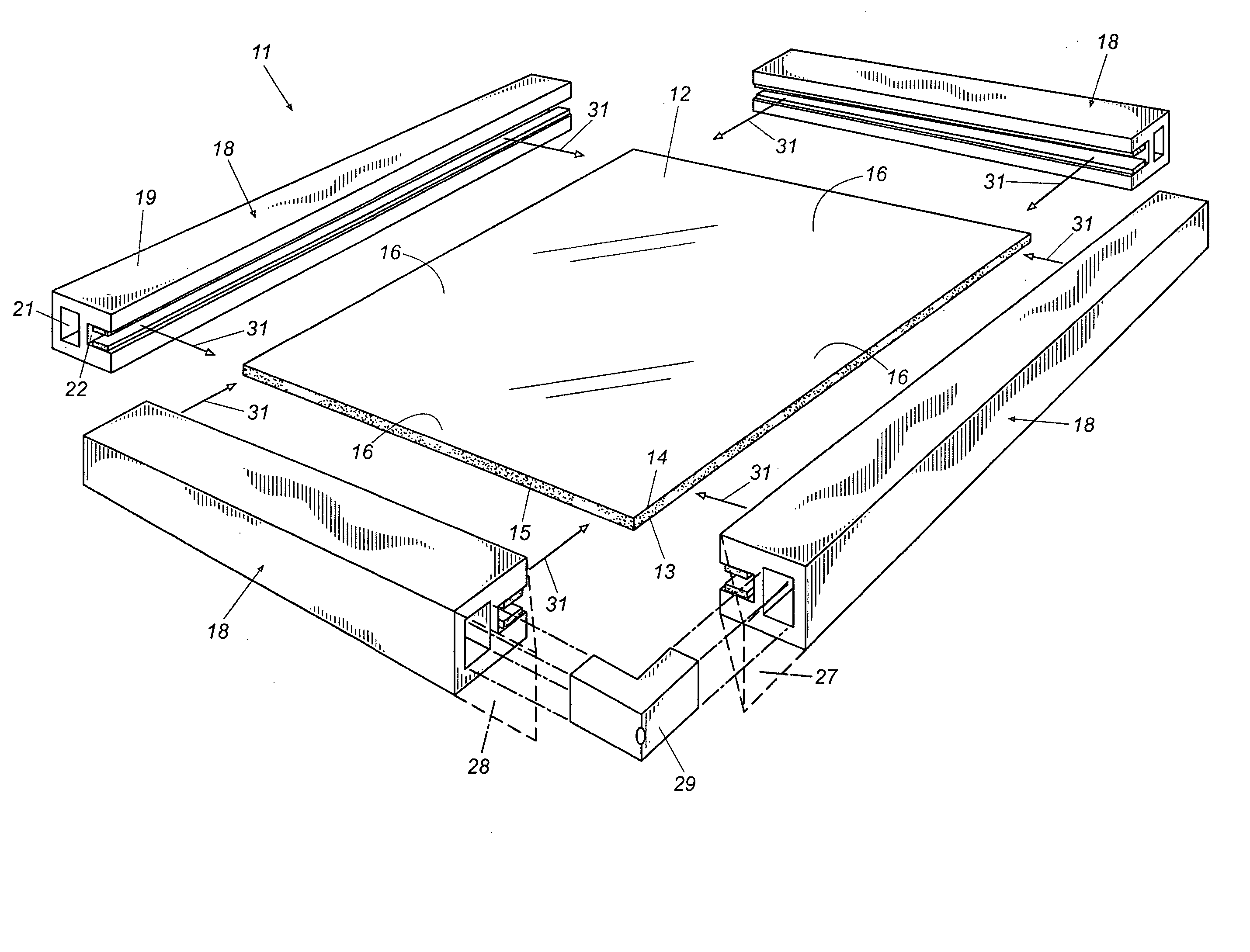
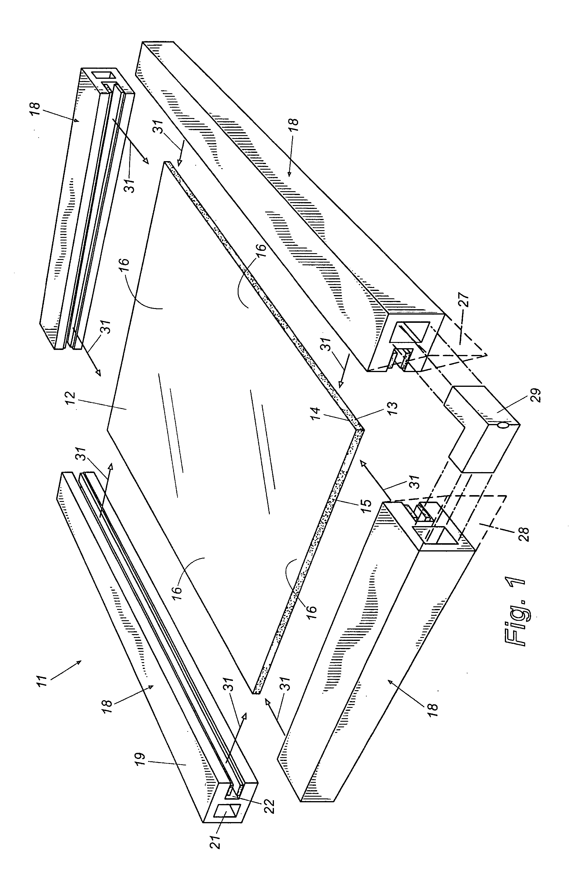
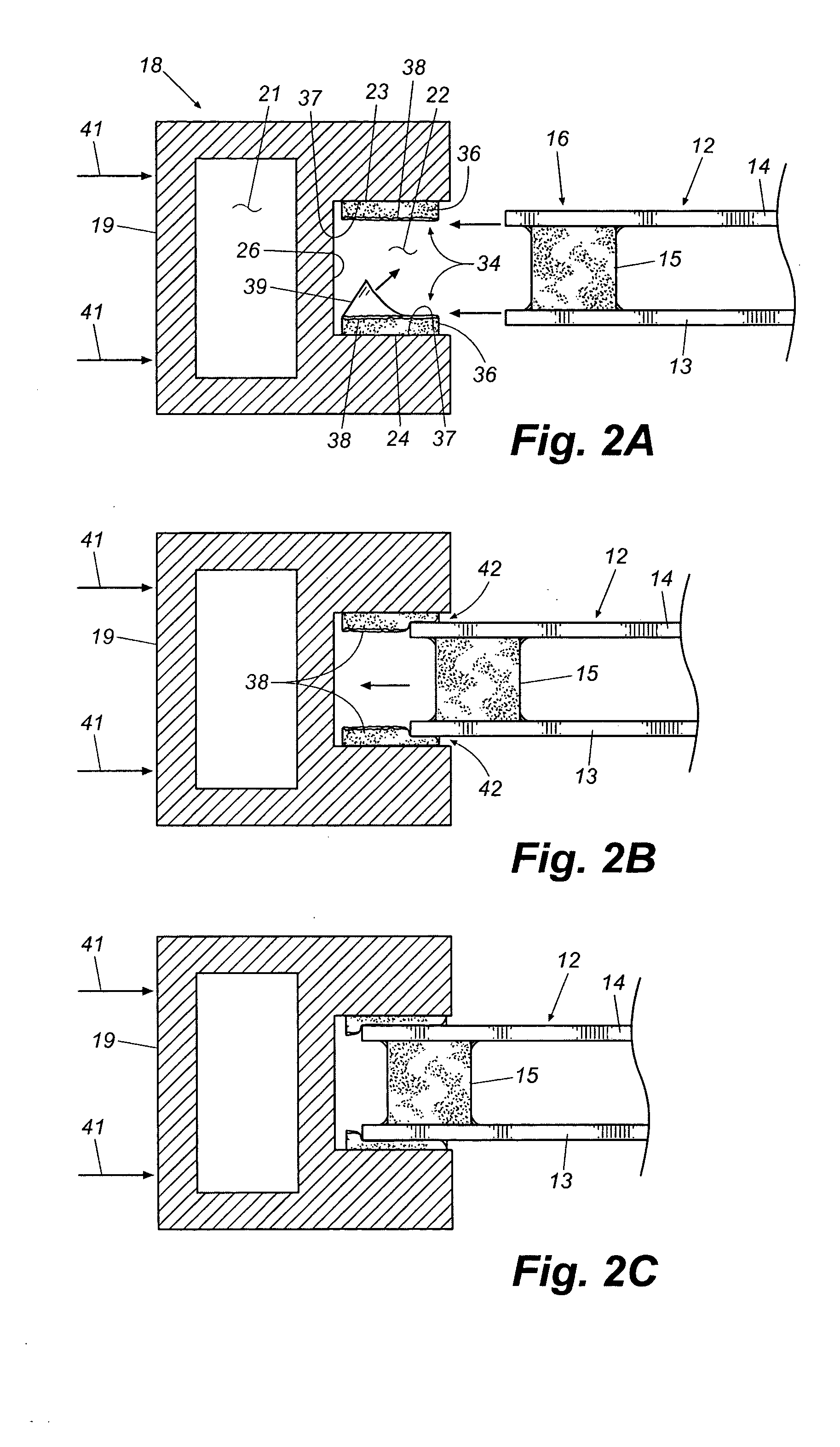
[0019] Reference is now made in more detail to the drawing figures, wherein like numerals refer, where appropriate, to like parts throughout the several views. FIG. 1 is a perspective partially exploded view of a window sash assembly illustrating preferred components and method steps of the present invention. The sash assembly 11 comprises a glass unit 12 made up of two spaced panes 13 and 14 of glass separated by an insulating space, which may be filled with an appropriate gas such as argon, as is known in the art. The panes 13 and 14 of glass are maintained in their spaced apart relationship and the space between them is sealed by a spacer 15, which extends around the periphery of the glass unit between the panes. While such a dual pane insulated glass unit is preferred, it should be understood that many other types of transparent or translucent material sheets might be used within the scope of the invention. For example, the glass unit might be comprised of a single pane of glass...


PUM

PropertyMeasurementUnit
Adhesion strengthaaaaaaaaaa
Adhesivityaaaaaaaaaa
Mechanical propertiesaaaaaaaaaa

Abstract

A method of applying a grooved lineal to the edge portion of a glass unit in the formation of a window component is provided. The method includes the steps of applying a triggerable sealant to the groove of the lineal, urging the edge portion of the glass unit into the groove, and triggering the sealant to form a seal between the groove and the edge portion of the glass unit. In one embodiment, the triggerable sealant is a dual state adhesive that can be placed in a first non-adhesive state by application of a temporary adhesion blocker. The lineal is urged onto the edge of the glass unit while the adhesive is in this first state and held in place until the adhesive transitions to its second adhesive state to bond and seal the glass within the groove.

Description

TECHNICAL FIELD [0001] This invention relates generally to fenestration and more specifically to methods of fabricating window components such as window sashes. BACKGROUND [0002] Groove glazed window sashes are common in fenestration. In general, a groove glazed sash comprises a sheet of glass, a multi-sheet integrated glass unit, or other transparent or translucent pane mounted within a sash frame formed by rails and stiles. The rails and stiles, otherwise referred to as the lineals, are configured with a continuous inside groove and the peripheral edges of the glass unit fit into and are sealed within the grooves. The ends of the lineals are configured to fit and join securely together to form a structurally sound and aesthetically pleasing joint at each corner of the sash. This may be accomplished in a variety of ways such as, for example, by mortise and tenon joinery, miter joints, by combinations thereof, or by other suitable joinery techniques. Adhesives and, in some cases, me...

Claims


Application Information

Patent Timeline
IPC IPC(8): E06B3/54E06B3/56
CPCE06B3/56E06B3/5454
Inventor HEIKKILA, KURT E.
Owner ANDERSEN CORPORATION
Why Eureka
Try Eureka