Amplitude controlled orifice valving

a technology of amplitude control and orifice valving, which is applied in the direction of shock absorbers, vibration dampers, springs/dampers, etc., can solve the problem of difficult task of obtaining damping force at relatively low piston velocities, and achieve the effect of soft damping and firm damping

Active Publication Date: 2006-04-20
TENNECO AUTOMOTIVE OPERATING CO INC
View PDF9 Cites 74 Cited by
  • Summary
  • Abstract
  • Description
  • Claims
  • Application Information

AI Technical Summary

Benefits of technology

[0008] The present invention provides the art with a multi-stage hydraulic damper or shock absorber that provides damping which varies according to the stroke amplitude. Soft damping is provided for small strokes and firm damping is provided for large strokes. The variable damping is provided by a sliding piston that is frictionally held in place on the piston rod inside of the pressure cylinder. While the shock absorber undergoes a small stroke, the sliding sleeve moves with the piston rod and the fluid flows through a separate flow path to provide a soft damping. When the shock absorber undergoes a large stroke, the sliding sleeve moves against a stop to close off the flow path which in turn provides a firm damping.

Problems solved by technology

Because of the exponential relation between pressure drop and flow rate, it is a difficult task to obtain a damping force at relatively low piston velocities, particularly at velocities near zero.

Method used


Image

  • Amplitude controlled orifice valving
  • Amplitude controlled orifice valving
  • Amplitude controlled orifice valving

Examples


Embodiment Construction

[0017] The following description of the preferred embodiment(s) is merely exemplary in nature and is in no way intended to limit the invention, its application, or uses.

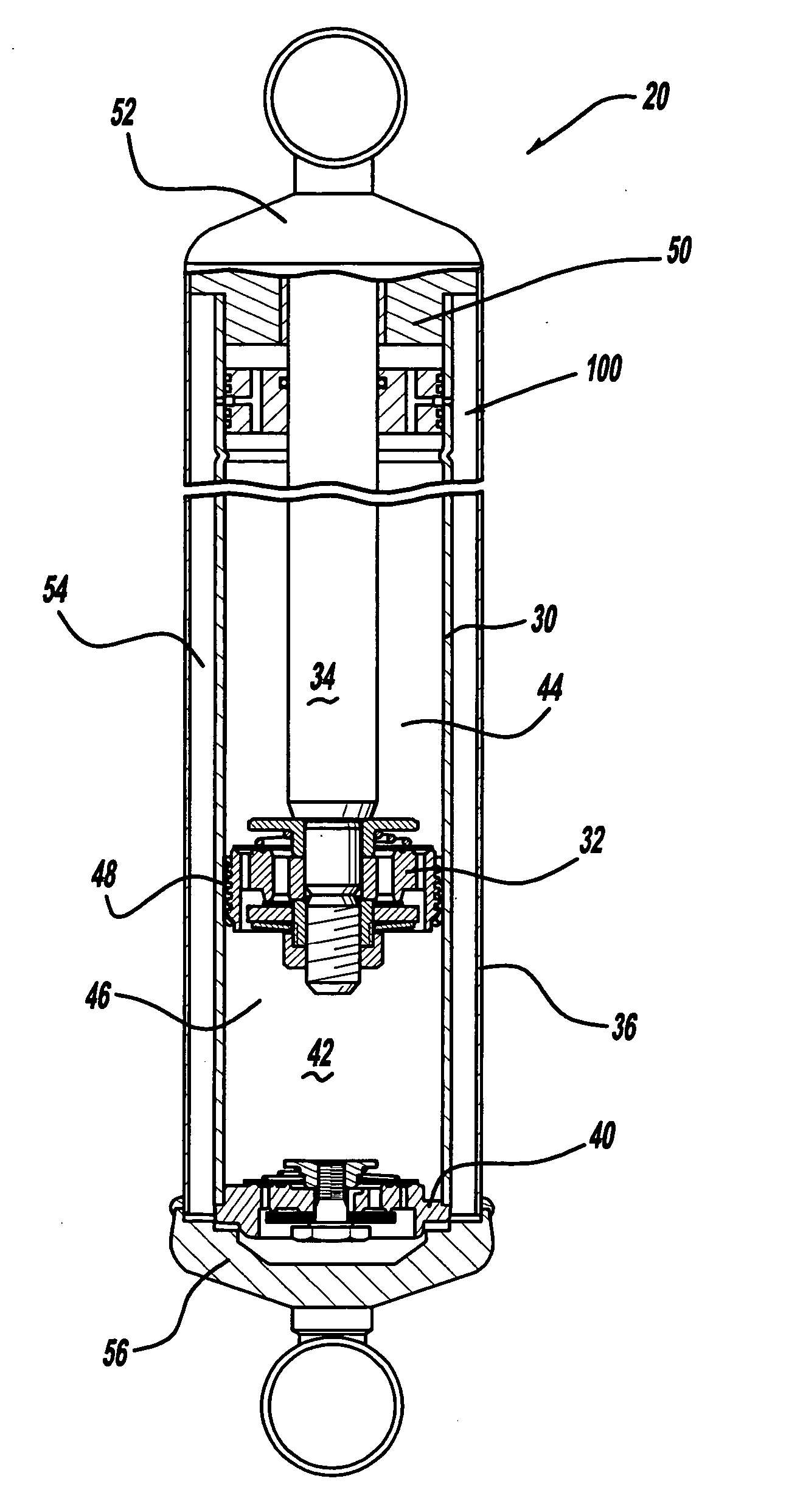
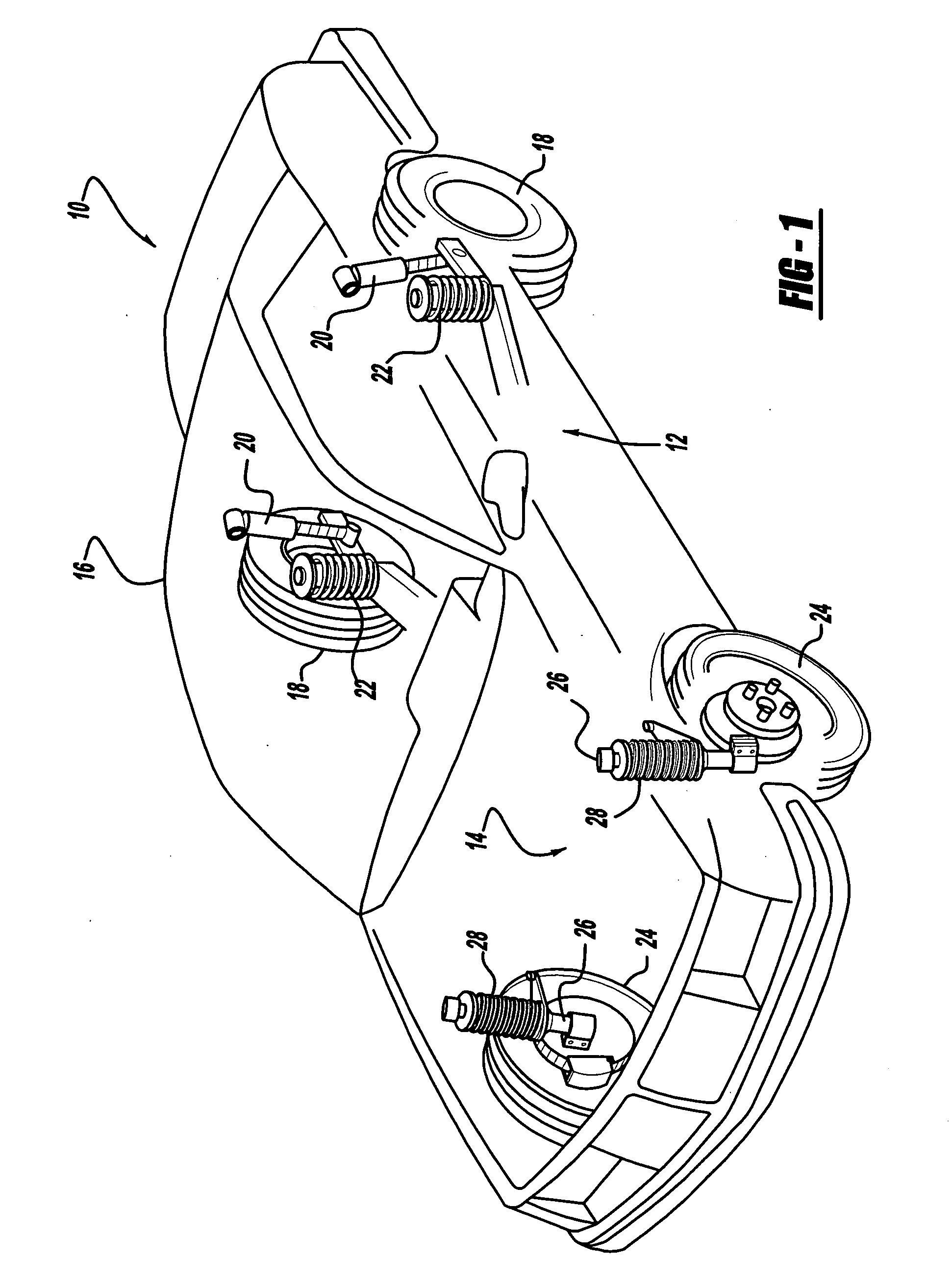
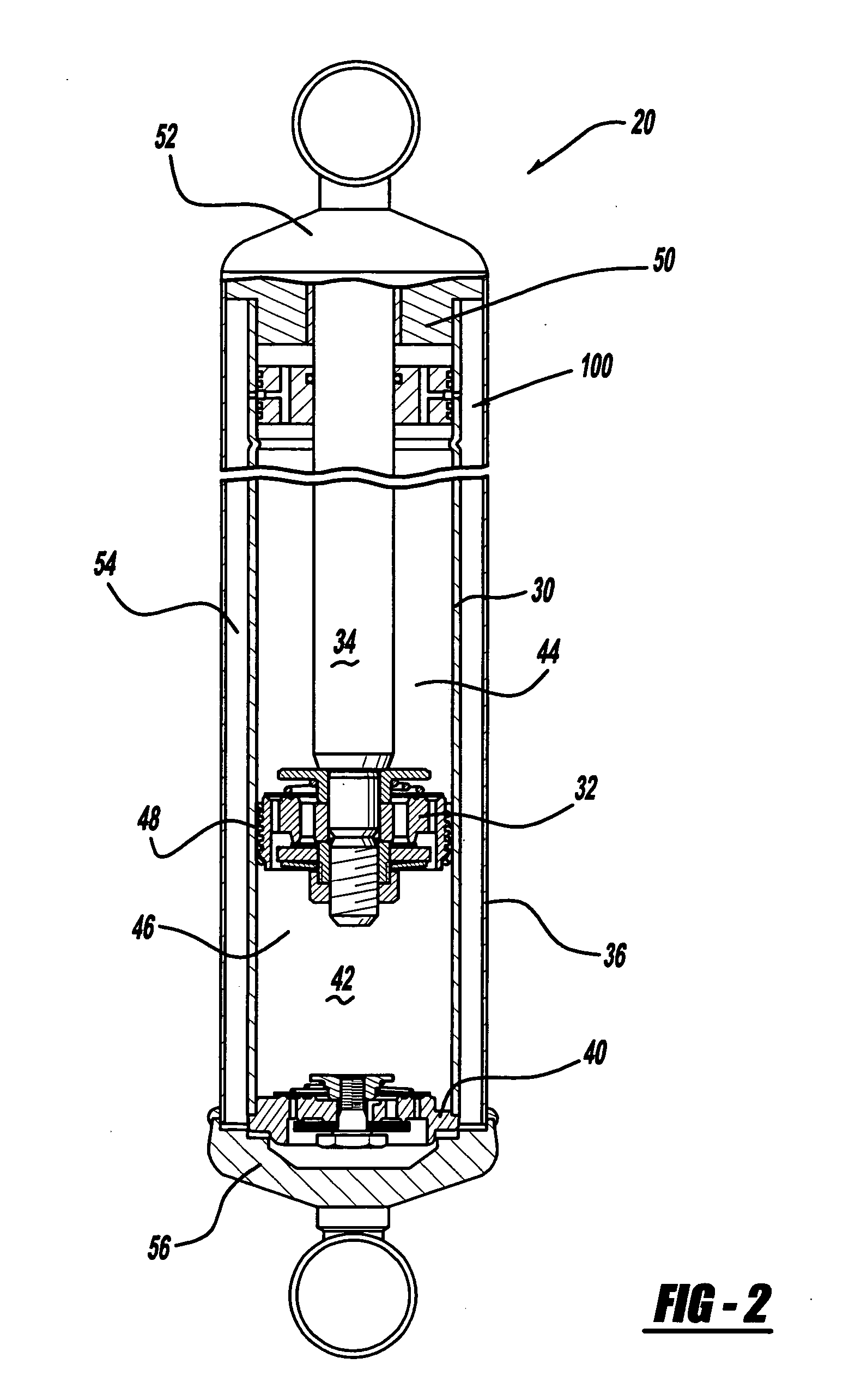
[0018] Referring now to the drawings in which like reference numerals designate like or corresponding parts throughout the several views, there is shown in FIG. 1 a vehicle incorporating a suspension system having the shock absorbers in accordance with the present invention which is designated generally by the reference numeral 10. Vehicle 10 includes a rear suspension 12, a front suspension 14 and a body 16. Rear suspension 12 has a transversely extending rear axle assembly (not shown) adapted to operatively support the vehicle's rear wheels 18. The rear axle assembly is operatively connected to body 16 by means of a pair of shock absorbers 20 and a pair of helical coil springs 22. Similarly, front suspension 14 includes a transversely extending front axle assembly (not shown) to operatively support the vehicle's f...


PUM


Abstract

A dual tube shock absorber includes a spool valve located between the upper working chamber and the reserve chamber. The spool valve moves with the piston rod to open and close a flow path between the upper working chamber and the reserve chamber. This provides a low damping characteristic for small movements of the piston rod which changes to a high damping characteristic for larger movement of the piston rod.

Description

FIELD OF THE INVENTION [0001] The present invention relates generally to automotive dampers or shock absorbers which receive mechanical shock. More particularly, the present invention relates to a unique hydraulic valve assembly which allows greater tunability of the shock absorber, especially in the mode of low hydraulic fluid flow. BACKGROUND OF THE INVENTION [0002] Shock absorbers are used in conjunction with automotive suspension systems to absorb unwanted vibrations which occur during driving. To absorb these unwanted vibrations, shock absorbers are generally connected between the sprung portion (body) and the unsprung portion (suspension) of the automobile. A piston is located within a pressure tube of the shock absorber, with the piston being connected to the sprung portion of the automobile through a piston rod and the pressure tube being connected to the unsprung portion of the automobile. Because the piston is able, through valving, to limit the flow of damping fluid betwe...

Claims


Application Information

Patent Timeline
Patent Type & Authority Applications(United States)
IPC IPC(8): F16F9/00
CPCF16F9/062F16F9/5126F16F9/483F16F9/185F16F9/187F16F9/3207F16F9/34F16F9/346
Inventor BREESE, DARRELL
Owner TENNECO AUTOMOTIVE OPERATING CO INC
Why Eureka
Try Eureka