
Mount for a wheelchair footrest

Inactive Publication Date: 2006-04-20
PRIDE MOBILITY PRODS CORP
View PDF27 Cites 44 Cited by
  • Summary
  • Abstract
  • Description
  • Claims
  • Application Information

AI Technical Summary

Problems solved by technology

Footrests, however, may get in the way of the user's ingress and egress of the wheelchair.

Method used


Image

  • Mount for a wheelchair footrest
  • Mount for a wheelchair footrest
  • Mount for a wheelchair footrest

Examples


Embodiment Construction

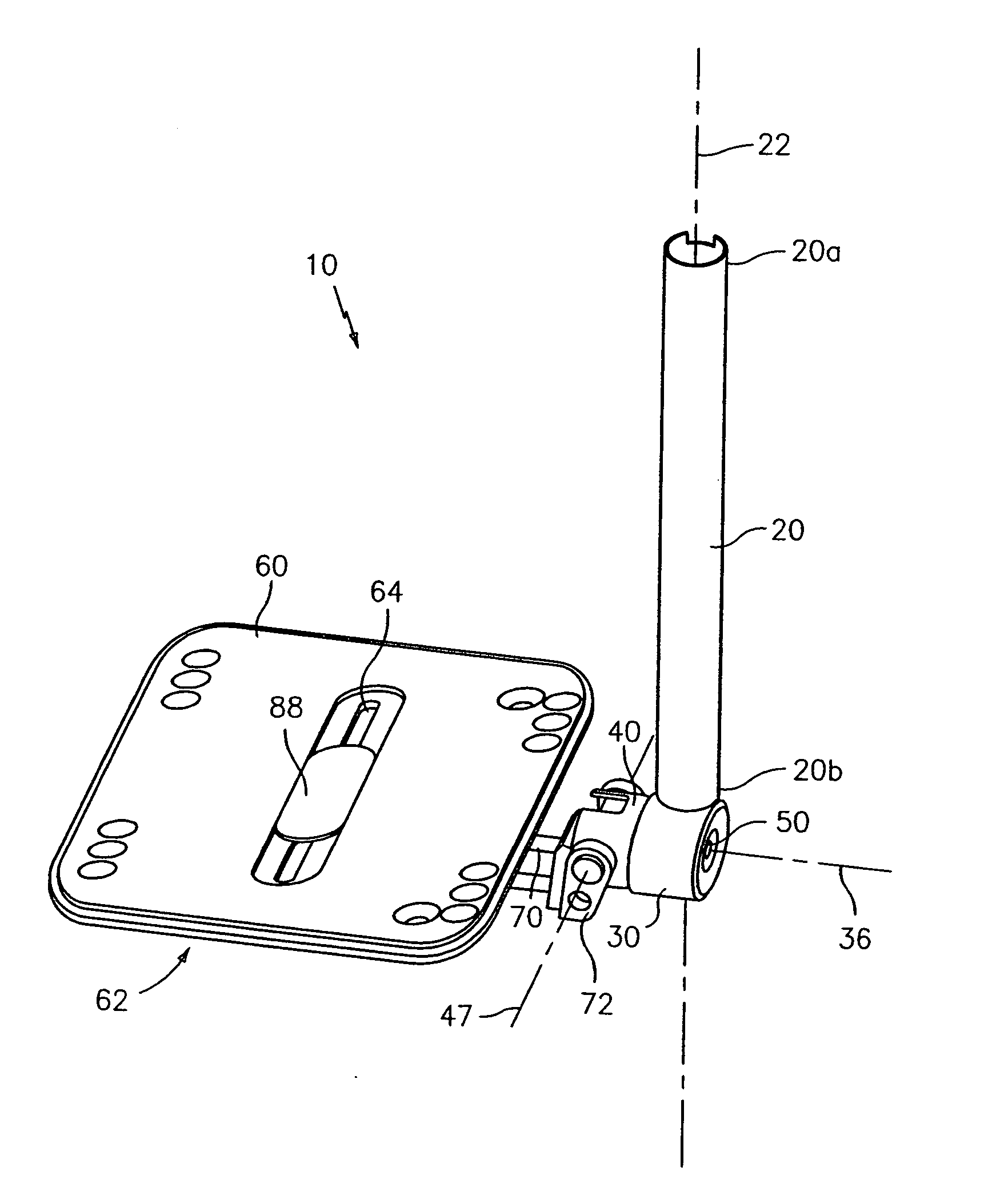
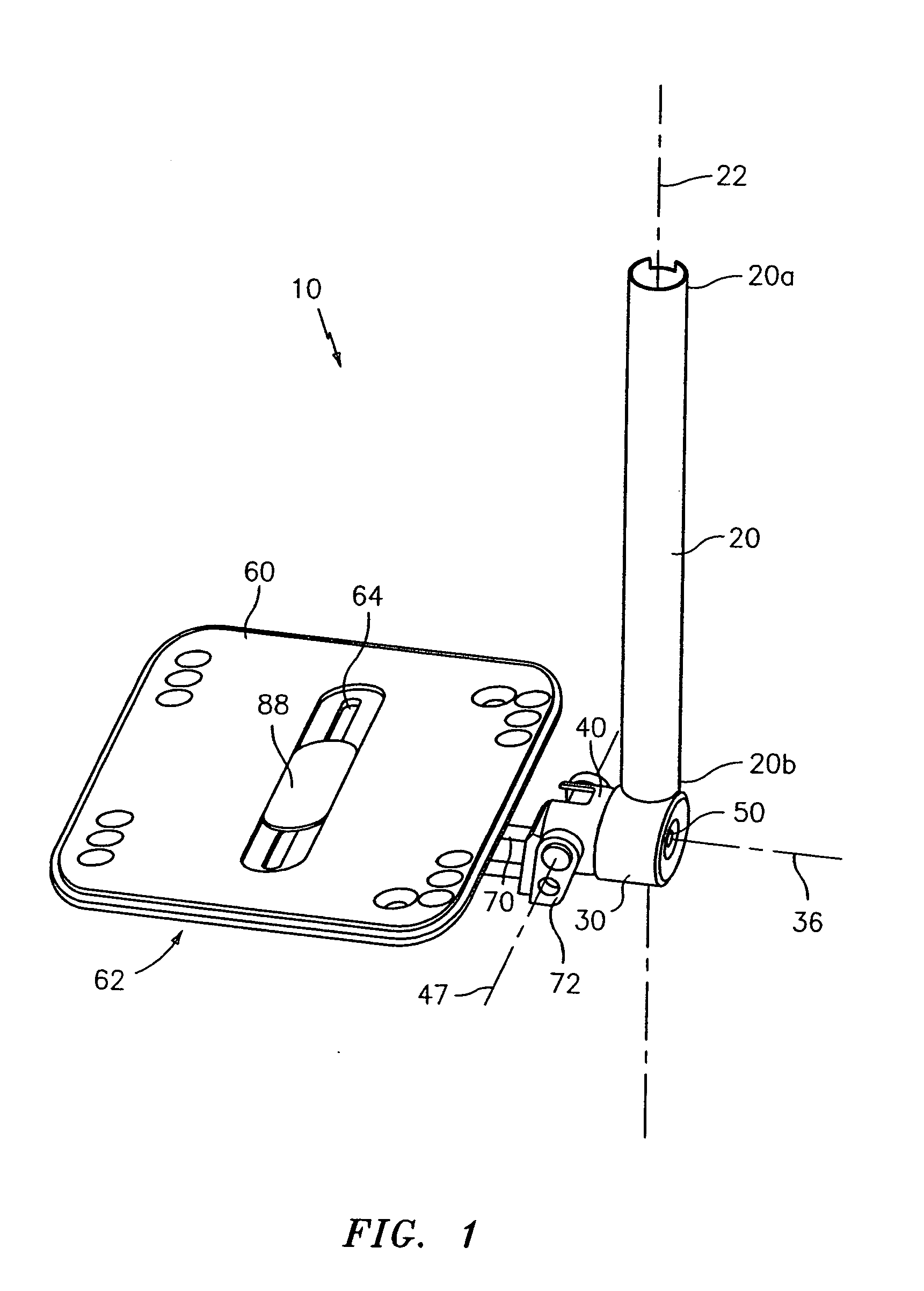
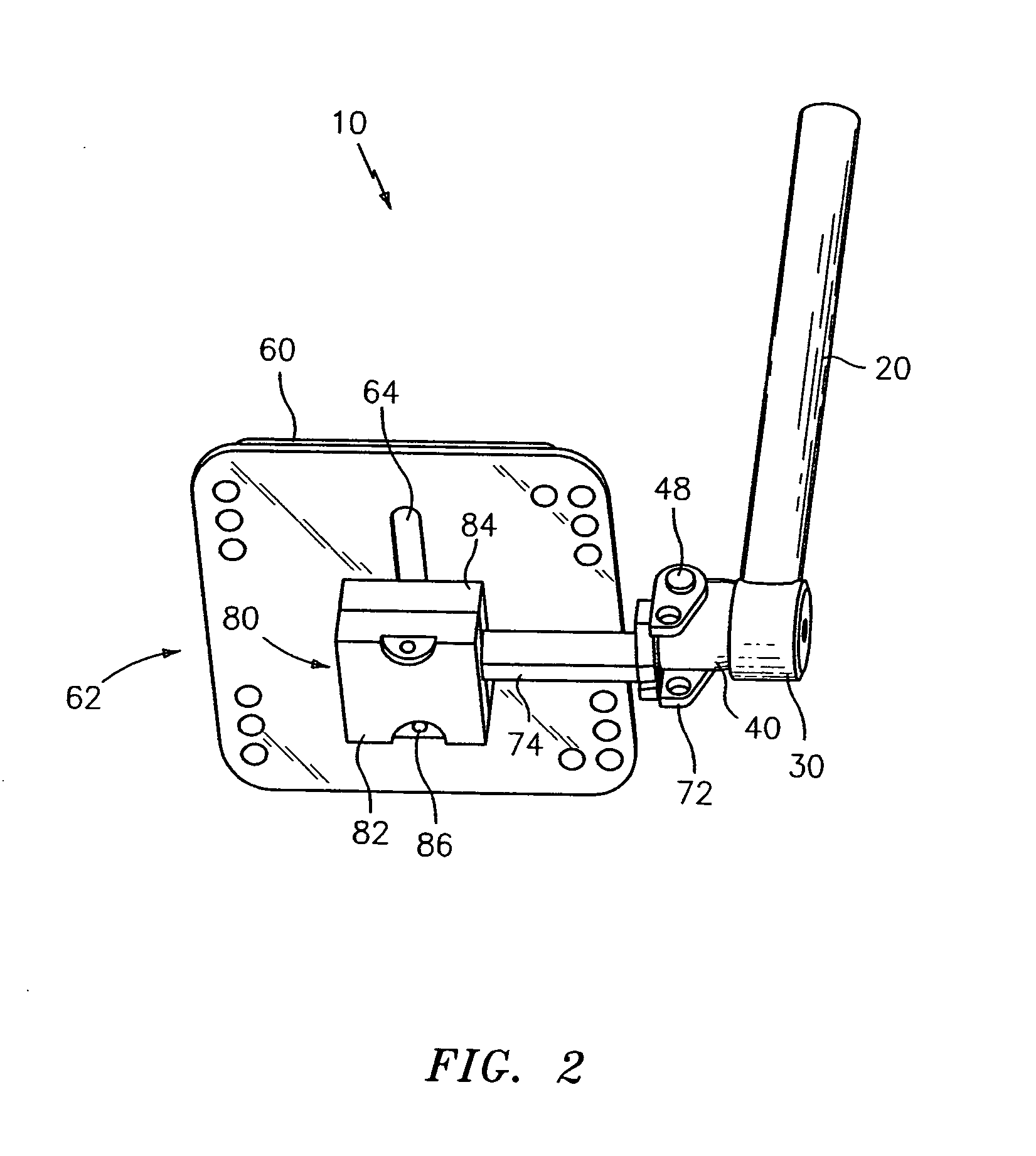
[0015] Referring to the drawings, where like numerals identify like elements, throughout a footrest assembly (or “footrest”10) is generally identified by the reference numeral 10 (in FIGS. 1-8). The footrest 10 comprises a footrest support member 20, a socket receptacle 30, a swivel element 40, a foot plate 60, and a foot plate support member 70. Preferably, the footrest 10 is used in combination with a wheelchair (not illustrated).

[0016] With particular reference to FIGS. 1-5, the footrest support member 20 is preferably an elongated tubular member having a first end 20a and a second end 20b. A support member axis 22 extends longitudinally from the first end 20a to the second end 20b. Preferably, the first end 20a of the footrest support member 20 is connected to a frame or a leg rest support attached to the frame of the wheelchair (not illustrated). Attachments may be made, for example, to a support by means of a projection that slideably fits within a T-slot on the frame or the ...


PUM


Abstract

A wheelchair footrest is provided having a footrest support member and a socket receptacle connected thereto. A swivel element is adjustably received for rotation within the socket receptacle. A foot plate is connected to the swivel element by a foot plate support member. The position of the swivel element is rotatably adjustable relative to the socket receptacle in yaw, pitch and roll directions. The swivel element has a socket engaging surface forming a portion of a sphere and the socket receptacle has an interior surface sized and shaped to mate with the socket engaging surface. The socket receptacle and the swivel element are fabricated from ferrous metals, and at least the interior surface of the socket receptacle and the socket engaging surface of the swivel element are subjected to a ferritic nitrocarburization surface treatment process.

Description

CROSS REFERENCE TO RELATED APPLICATION [0001] This application claims priority from U.S. Provisional Patent Application No. 60 / 619,704, filed Oct. 18, 2004.FIELD OF THE INVENTION [0002] The present invention relates to footrests for vehicles, such as manual or powered wheelchairs. BACKGROUND OF THE INVENTION [0003] It is known to provide wheelchairs with footrests. Generally, footrests are used in wheelchairs to support the user's feet and keep them elevated above the supporting surface. Footrests, however, may get in the way of the user's ingress and egress of the wheelchair. Therefore, it is known to have footrests that are positionable out of the way of a user. It is also known to have footrests on a wheelchair that rotate about an axis from a usable position to a storage position. Additionally, there are various required positions of the footrest required for the comfort of users of different shapes and sizes. To address this problem, some wheelchairs have been constructed with ...

Claims


Application Information

Patent Timeline
IPC IPC(8): A61G5/10
CPCA61G5/12A61G2005/128A61G5/128
Inventor HARRIS, VINCE
Owner PRIDE MOBILITY PRODS CORP
Learn More