
Apparatus for supplying power to controller

Inactive Publication Date: 2006-04-27
SAMSUNG ELECTRONICS CO LTD
View PDF8 Cites 2 Cited by
  • Summary
  • Abstract
  • Description
  • Claims
  • Application Information

AI Technical Summary

Benefits of technology

[0014] The present invention has been developed to overcome the above-mentioned problems of the related art, and accordingly, it is an object of the present invention to provide an apparatus for supplying power to a controller, which provides more stable power supply switching to a controller, prevents use of an over-discharged battery as a power supply, and stabilizes reset operation of the controller.

Problems solved by technology

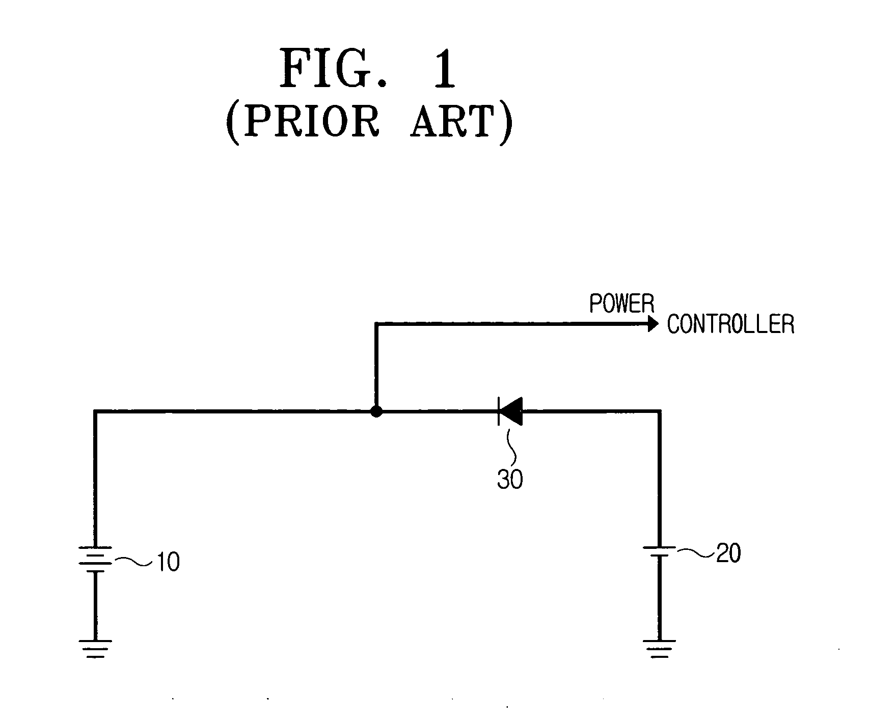
Because only the diode 30 operates to switch supply power supply to the controller, the power supply switching was not stable enough in the conventional power supply apparatus.

Method used


Image

  • Apparatus for supplying power to controller
  • Apparatus for supplying power to controller
  • Apparatus for supplying power to controller

Examples


Embodiment Construction

[0033] Certain embodiments of the present invention will now be described in greater detail with reference to the accompanying drawings.

[0034] The matters defined in the description such as a detailed construction and elements are provided to assist in a comprehensive understanding of the invention. Thus, it is apparent that various changes and modifications to the embodiments described herein can be made without departing from the scope and spirit of the present invention. Also, descriptions of well-known functions or constructions are omitted for clarity and conciseness.

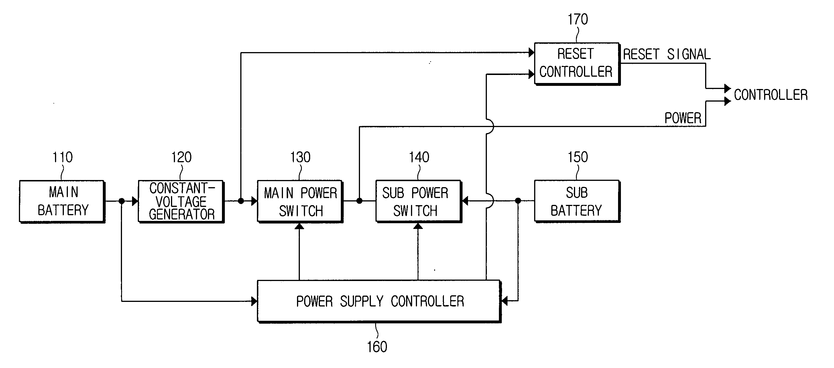
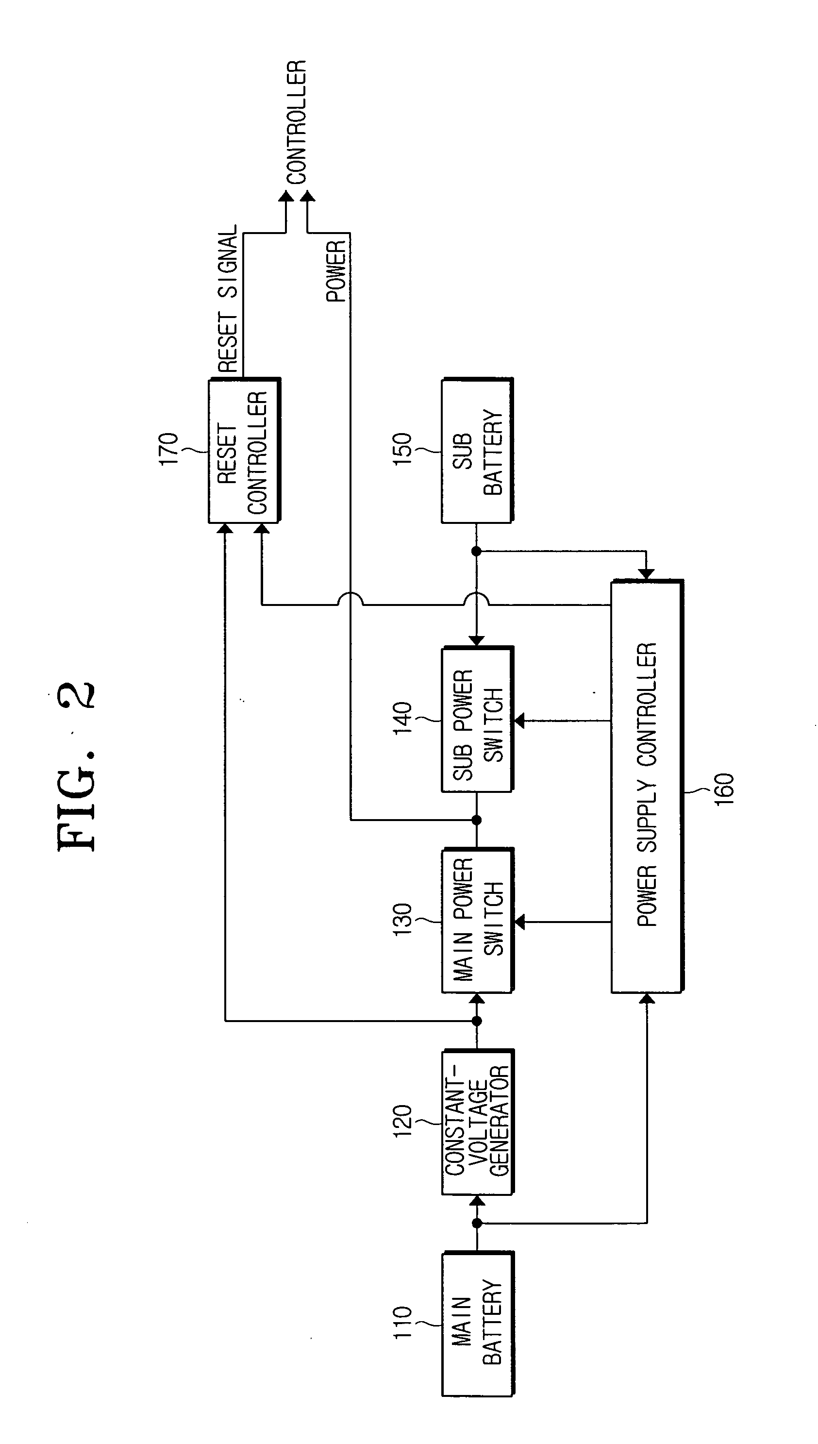
[0035]FIG. 2 is a block diagram of an apparatus for supplying power to a controller according to an embodiment of the present invention.

[0036] Referring to FIG. 2, the power supplying apparatus includes a constant-voltage generator 120, a main power switch 130, a sub power switch 140, a power supply controller 160 and a reset controller 170.

[0037] Main and sub batteries 110 and 150 are provided to the power sup...


PUM


Abstract

An apparatus for supplying power to a controller has a main power switch provided on a power supply path of a main power to a controller, a sub power switch provided on a power supply path of a sub power to the controller, and a power supply controller that opens the main power switch and closes the sub power switch so that the sub power is supplied to the controller when not receiving the main power. Accordingly, the power supply to the controller can be more stably switched. Additionally, an over-discharged battery is not used in power supply, and the controller can have a more stable reset operation.

Description

CROSS-REFERENCE TO RELATED APPLICATIONS [0001] This application claims the benefit under 35 U.S.C. §119(a) of Korean Patent Application No. 2004-84803, filed on Oct. 22, 2004, in the Korean Intellectual Property Office, the entire disclosure of which is hereby incorporated by reference. BACKGROUND OF THE INVENTION [0002] 1. Field of the Invention [0003] The present invention relates to a power supply apparatus. More particularly, the present invention relates to a power supply apparatus which supplies power to a controller using main and sub batteries as a power source. [0004] 2. Description of the Related Art [0005] A controller is an element which drives and controls electrical parts according to user instructions, and is often considered to be the most essential part of an electronic device. Even when the electronic device is not in operation, that is, even in a power-off state, the controller sometimes remains operating. For example, the controller may be on to drive a timer to ...

Claims


Application Information

Patent Timeline
IPC IPC(8): G06F1/26
CPCG06F1/263H02J9/061H02J7/34
Inventor KIM, JONG-BOO
Owner SAMSUNG ELECTRONICS CO LTD
Learn More