
Polarity switching method in consumable electrode AC pulse arc welding

Active Publication Date: 2007-10-25
DAIHEN CORP
View PDF11 Cites 27 Cited by
  • Summary
  • Abstract
  • Description
  • Claims
  • Application Information

AI Technical Summary

Benefits of technology

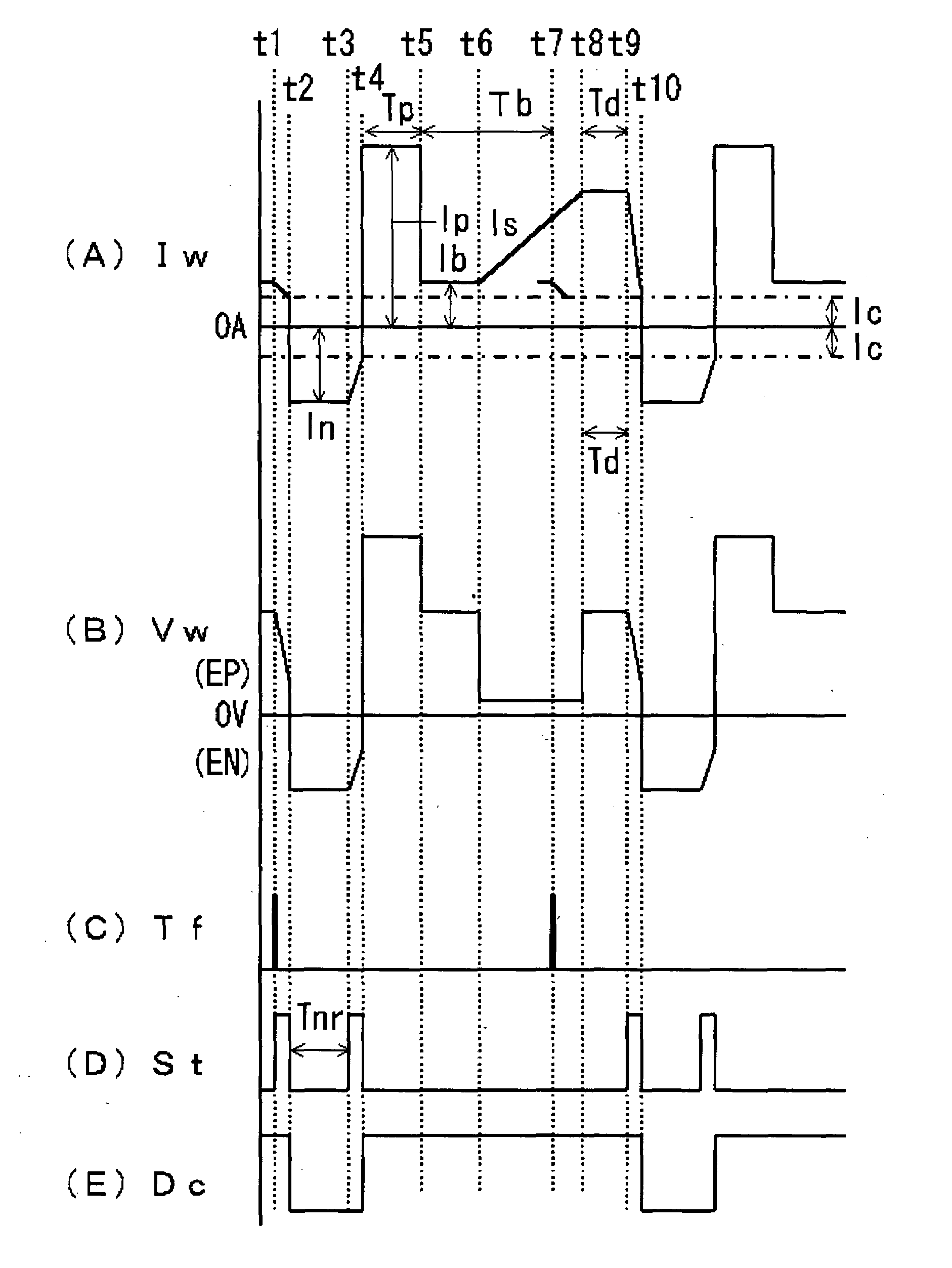
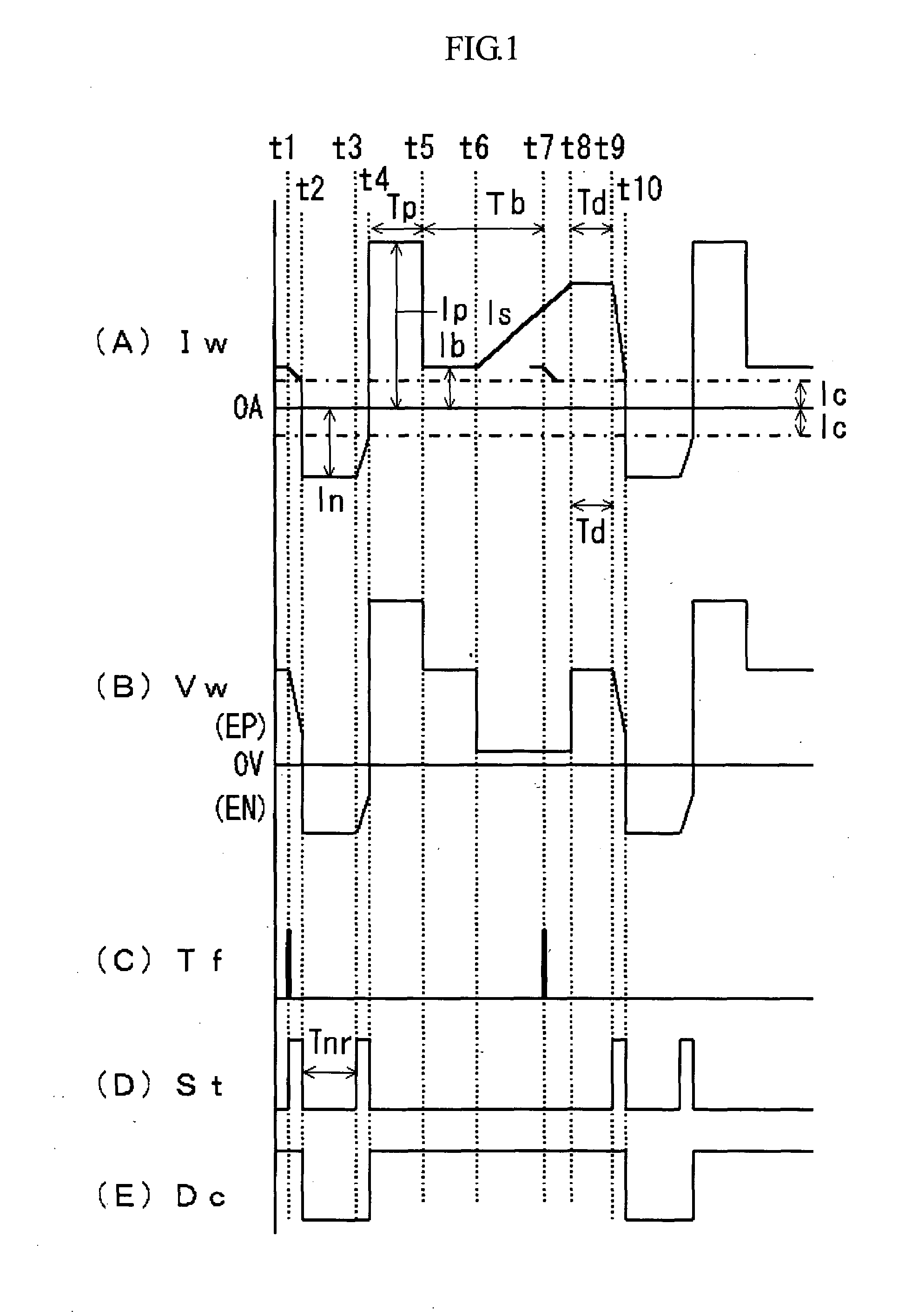
[0019]The present invention has been provided in the above-described situation. It is therefore an object of the present invention to provide a polarity switching control method in consumable electrode AC pulse arc welding, which is capable of making stable polarity switching even if short-circuiting occurs at the time of polarity switching.
[0021]With the above arrangement, the polarity switching is not performed while short-circuiting is present, but performed after the short-circuiting comes to an end and the arc is generated. Accordingly, it is possible to perform stable polarity switching and prevent prolonged short-circuiting or arc interruption. In particular, the present invention is advantageous for a case where the welding voltage is set at a low value for the purpose of reducing the heat conduction to the base metal or increasing the welding speed.
[0022]Preferably, the polarity switching may be performed after a lapse of a predetermined delay period starting from the generation of the arc. In this manner, it is possible to prevent short-circuiting from occurring immediately after the recurrence of the arc.
[0023]Preferably, a welding current applied at the generation of the arc may be maintained during the delay period. Since the welding current applied at the generation of the arc is high current, it is possible to attain a great arc length.

Problems solved by technology

However, if short-circuiting occurs during the polarity switching, there is a high likelihood for occurrence of prolonged short-circuiting and arc interruption.
When short-circuiting occurs during polarity switching, the decreasing of the welding current Iw causes the short-circuiting to persist, thereby making the arc unstable or even broken by melting.
In pulse arc welding, however, short-circuiting occurs irregularly.

Method used


Image

  • Polarity switching method in consumable electrode AC pulse arc welding
  • Polarity switching method in consumable electrode AC pulse arc welding
  • Polarity switching method in consumable electrode AC pulse arc welding

Examples


Embodiment Construction

[0029]Preferred embodiments of the present invention will be described below with reference to the accompanying drawings.

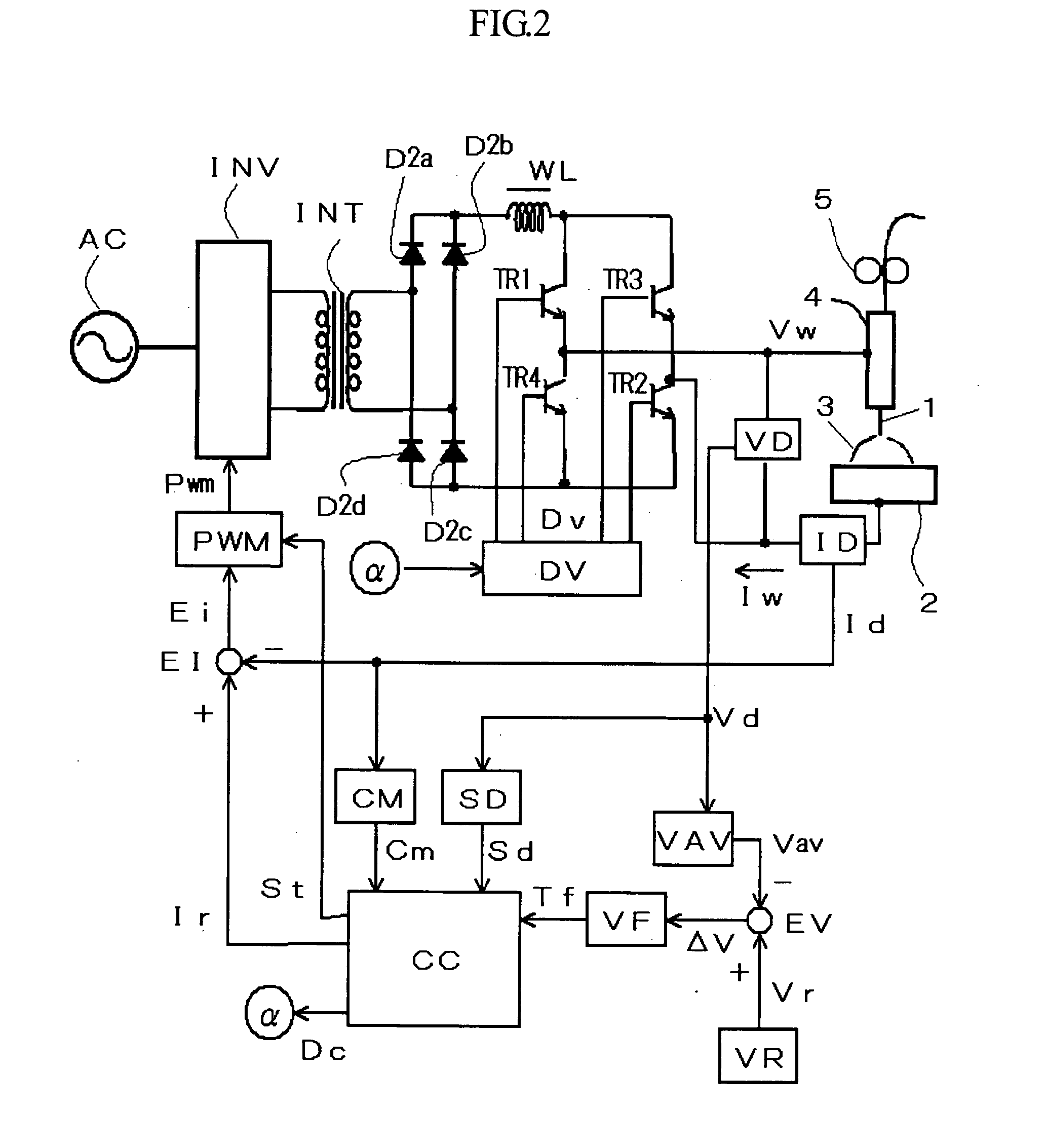
[0030]FIG. 2 is a block diagram of a welding power source for implementing a polarity switching control method in consumable electrode AC pulse arc welding according to the present invention.

[0031]An inverter circuit INV receives commercially available AC power such as three-phase 200 volts as an input, and performs the rectification and smoothing of the input. In addition, the inverter circuit INV performs an inverter control in accordance with a pulse width modulation signal Pwm to be described later, and outputs high-frequency alternating current. A high-frequency transformer INT decreases the high-frequency AC to a voltage suitable to arc welding. Secondary rectifiers D2a through D2d rectify the reduced high-frequency AC. A reactor WL smoothes the rectified DC output. Transistors TR1 through TR4 constitute a secondary inverter circuit which outputs a welding v...


PUM

PropertyMeasurementUnit
Polarityaaaaaaaaaa
Currentaaaaaaaaaa

Abstract

A polarity switching control method is provided for consumable electrode AC pulse arc welding. By the method, a peak current and a base current are applied during an electrode-positive polarity period, while an electrode-negative current is applied during an electrode-negative polarity period. For performing the welding, polarity switching is performed to alternate the electrode-positive polarity period and the electrode-negative polarity period. When a consumable electrode and a base metal are in short circuit with each other, the polarity switching is performed after the short circuit is broken and an arc is generated.

Description

BACKGROUND OF THE INVENTION[0001]1. Field of the Invention[0002]The present invention relates to a polarity switching control method for improving stability during polarity switching in consumable electrode AC pulse arc welding.[0003]2. Description of the Related Art[0004]For consumable electrode AC pulse arc welding (referred to as “AC pulse arc welding” below), a welding wire is supplied at constant speed, and two periods, i.e. an electrode-positive polarity period Tep and an electrode-negative polarity period Ten, are caused to alternate with each other. During the electrode-positive polarity period Tep, peak current Ip and base current Ib are applied, whereas during the electrode-negative polarity period Ten, electrode-negative current In is applied. In order to achieve high quality welding, it is important in AC pulse arc welding that polarity switching is performed properly so that no arc interruption occurs. To this end, conventionally, a high voltage is applied between the w...

Claims


Application Information

Patent Timeline
IPC IPC(8): B23K9/10
CPCB23K9/092
Inventor NISHISAKA, FUTOSHIMONDORI, HIROYASU
Owner DAIHEN CORP
Learn More