Low-voltage distribution network line reactive compensation device and compensation method

A low-voltage distribution network and compensation device technology, applied in reactive power compensation, reactive power adjustment/elimination/compensation, etc., can solve problems such as complex low-voltage distribution network structure, unsatisfactory compensation effect, and difficulty in starting and running high-power equipment , to avoid switching instability and over-compensation problems, solve the problem of not starting normally, and improve the switching function

Active Publication Date: 2014-04-09
STATE GRID CORP OF CHINA +1
View PDF5 Cites 4 Cited by
  • Summary
  • Abstract
  • Description
  • Claims
  • Application Information

AI Technical Summary

Problems solved by technology

[0002] Due to the complex structure of the low-voltage distribution network, there are few types of low-voltage reactive power compensation products in the prior art, and automatic switching is performed by considering parameters such as reactive power requirements, voltage and current values, and the capacitor compensation capacity is large and the grouping is small. Switching can only be performed when the reactive power demand is greater than 10kvar. On the one hand, the load in rural areas fluctuates frequently, resulting in unstable switching of the low-voltage reactive power compensatio

Method used


Image

  • Low-voltage distribution network line reactive compensation device and compensation method
  • Low-voltage distribution network line reactive compensation device and compensation method

Examples


Example Embodiment

[0028] The present invention will be further described in detail below in conjunction with specific embodiments, which are for explanation rather than limitation of the present invention.

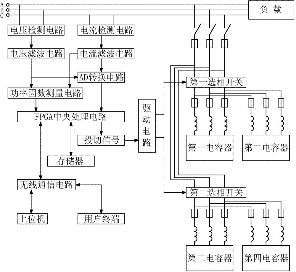
[0029] The present invention is a low-voltage distribution network line reactive power compensation device, such as figure 1 As shown, it includes a compensation unit connected in parallel on a low-voltage line in a low-voltage power distribution network, and a control unit that controls the switching of the compensation unit; the compensation unit includes a phase selection switch and a capacitor connected in turn on the low-voltage line; The control unit includes a wireless communication circuit for receiving the low-voltage distribution network reactive power daily load curve data sent by the host computer; an FPGA central processing circuit for processing curve data and sending time switching signals; for storing curve data Memory; a drive circuit for switching control of the phase selectio...


PUM


Abstract

The invention discloses a low-voltage distribution network line reactive compensation device, comprising a compensation unit connected in parallel in a low-voltage line in a low-voltage distribution network and a control unit controlling the switching of the compensation unit. The compensation unit comprises phase selection switches and capacitors which are sequentially connected in the low-voltage line. The control unit comprises a wireless communication circuit used for receiving low-voltage distribution network reactive power daily load curve data transmitted from an upper computer; an FPGA central processing circuit used for processing the curve data and transmitting a time switching signal; a storage used for storing the curve data; and a drive circuit used for controlling the switching of the phase selection switches based on the switching signal. A reactive compensation method of the invention comprises the following steps of 1) transmitting the time switching signal and calculating time reactive power needing compensation; 2) transmitting a comparison switching signal and calculating comparison reactive power needing compensation; 3) transmitting a request switching signal and request reactive power; 4) selecting and executing one switching signal; and 5) selecting the number of devoted capacitors.

Description

Technical field [0001] The invention relates to an electrical control device in the field of power supply and distribution, in particular to a reactive power compensation device and a compensation method for low-voltage distribution network lines. Background technique [0002] Due to the complex structure of the low-voltage distribution network, there are few types of low-voltage reactive power compensation products in the prior art. They are automatically switched on and off by considering the parameters of reactive power requirements, voltage and current values, and the capacitor compensation capacity is large and the grouping is small. Switching can only be performed when the reactive power requirement is greater than 10kvar. On the one hand, frequent load fluctuations in rural areas result in unstable switching of the low-voltage reactive power compensation device, which is prone to over-compensation. At the same time, the product price is relatively high, and the compensation...

Claims


Application Information

Patent Timeline
IPC IPC(8): H02J3/18
CPCY02E40/30
Inventor 杨李周楚文斌张永飞
Owner STATE GRID CORP OF CHINA
Why Eureka
Try Eureka