
Non-magnetic low-vortex positioning device

A positioning device and vortex technology, applied in the direction of induction heating, etc., can solve the problems of unstable material installation, high production cost, uneven heating, etc., and achieve the effects of improving service life, reducing induction heating, and reducing production costs

Active Publication Date: 2021-01-01
JIANGXI LIANOVATION SUPERCONDUCTOR APPL CO LTD
View PDF5 Cites 0 Cited by
  • Summary
  • Abstract
  • Description
  • Claims
  • Application Information

AI Technical Summary

Problems solved by technology

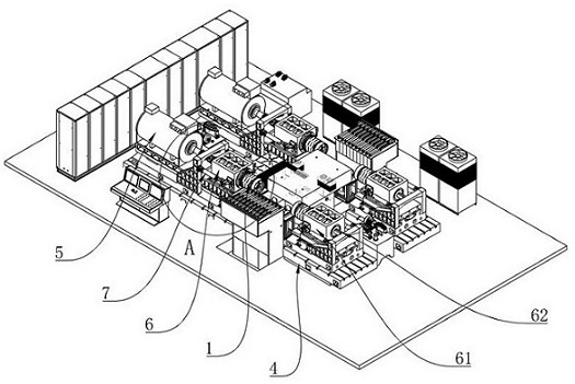
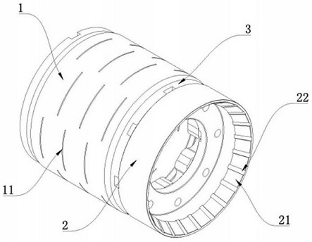
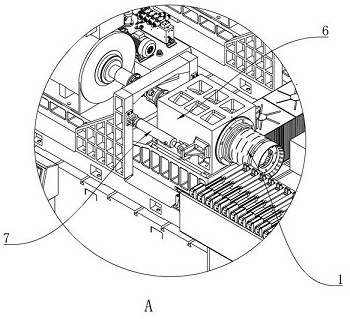
[0003] The invention provides a non-magnetic low-vortex positioning device to solve the problems in the prior art that the material is not installed firmly, the heating is uneven, and the production cost is high.

Method used


Image

  • Non-magnetic low-vortex positioning device
  • Non-magnetic low-vortex positioning device
  • Non-magnetic low-vortex positioning device

Examples


Embodiment Construction

[0026] The specific implementation manners of the present invention will be further described in detail below in conjunction with the accompanying drawings and embodiments. The following examples are used to illustrate the present invention, but are not intended to limit the scope of the present invention.

[0027] In the description of this application, it is to be understood that the terms "center", "upper", "lower", "front", "rear", "left", "right", "vertical", "horizontal", The orientations or positional relationships indicated by "top", "bottom", "inner", "outer", etc. are based on the orientations or positional relationships shown in the drawings, and are only for the convenience of describing the application and simplifying the description, rather than indicating or implying References to devices or elements must have a particular orientation, be constructed, and operate in a particular orientation and therefore should not be construed as limiting the application.

[0...


PUM


Abstract

The invention relates to the technical field of superconducting induction heating, and discloses a non-magnetic low-vortex positioning device, which comprises a positioning body, a clamping part whichis connected with a manipulator; and a connecting part which is connected between the clamping part and the positioning body. According to the invention, by means of the non-magnetic low-vortex positioning device, induction heating of the non-magnetic low-vortex positioning device can be reduced, heat conducted to the non-magnetic low-vortex positioning device from machined materials is weakened,and damage to the non-magnetic low-vortex positioning device is avoided. The service life of the non-magnetic low-vortex positioning device is prolonged, and the production cost is further reduced.

Description

technical field [0001] The invention relates to the technical field of superconducting induction heating, in particular to a nonmagnetic low vortex positioning device. Background technique [0002] At present, the superconducting induction heater in the prior art is relatively bulky and bulky, and the small-volume superconducting induction heater cannot heat larger materials. In the existing equipment, in order to touch the material, it will The offset distance of the jacking force is generated, and the offset distance of the jacking force acts on the equipment for a long time, which has a certain degree of influence on the precision and service life of the equipment, thereby reducing the heating efficiency and working effect of the equipment, and the existing equipment cannot meet the requirements of low speed. Large overload requirements, frequent start and stop operations, and complex heating processes cannot be performed. When the top touches the material, the material i...

Claims


Application Information

Patent Timeline
IPC IPC(8): H05B6/02
CPCH05B6/02
Inventor 洪智勇常同旭胡磊马化韬李银波伍宇扬
Owner JIANGXI LIANOVATION SUPERCONDUCTOR APPL CO LTD
Learn More