GPS receiver having a phase lock loop hold off

a technology of phase lock loop and receiver, which is applied in the field of global navigation satellite system (gnss) receivers, can solve the problems of inability to accurately fix the location, phase lock loop can cycle-slip or lose lock, and may not be tolerable, so as to achieve fewer outages and fewer location jumps

Active Publication Date: 2006-05-11
TRIMBLE NAVIGATION LTD
View PDF2 Cites 19 Cited by
  • Summary
  • Abstract
  • Description
  • Claims
  • Application Information

AI Technical Summary

Benefits of technology

[0015] An advantage of the present invention is that GNSS-based location fixes are more consistent with fewer outages and fewer location jumps.

Problems solved by technology

Noise on the pseudoranges results in less accurate location fixes.
However, phase lock loops can cycle-slip or lose lock unless the GNSS signal is relatively strong.
These problems may be tolerable when the signal strength does not often change between weak and strong.
Unfortunately, there are cases where the GNSS signal strength changes rapidly such as when the GNSS signal is subject to multipath or the GNSS receiver is beneath a tree canopy.
When the GNSS receiver is beneath a tree canopy, the loop transition problem may occur each time the GNSS satellite or the GNSS receiver moves just enough to pass by a branch or leaf in the line-of-sight between the satellite and the receiver.

Method used


Image

  • GPS receiver having a phase lock loop hold off
  • GPS receiver having a phase lock loop hold off
  • GPS receiver having a phase lock loop hold off

Examples


second embodiment

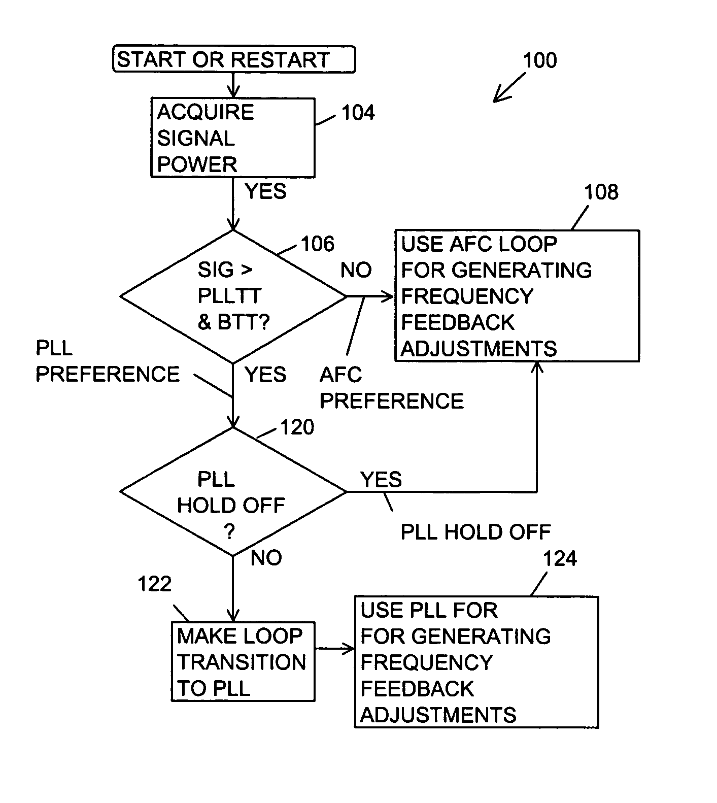
[0063]FIG. 7 is a flow chart of the step 120 for determining whether to make the loop transition from the AFC loop to the phase lock loop or to generate a PLL hold-off. A step 134B replaces the step 134A. The step 134B checks whether settling semaphores are active for any of the GPS signal channels 21-31 that were being used for location fixes. When one or more of the settling semaphores is active, the GPS receiver 10 continues in the step 108 to use the AFC loop for determining pseudoranges for computing location fixes. When no settling semaphores are active, the GPS receiver 10 in the step 136 checks whether the TCNT for the particular GPS satellite of the GPS signal channel 20 is less than the selected transition count threshold and so on as described above.

third embodiment

[0064]FIG. 8 is a flow chart of the step 120 for determining whether to make the loop transition from the AFC loop to the phase lock loop or to generate a PLL hold-off. A step 150 checks the conditional PDOP for the assigned GPS satellite against the conditional PDOP threshold. When the conditional PDOP is lower than the threshold, the GPS receiver 10 transitions to the phase lock loop and then uses the phase lock loop for determining pseudoranges for computing location fixes in the steps 122 and 124. When the conditional PDOP is greater than the threshold, the step 134A, B checks for elapsed time or active semaphores, the step 136 for testing TCNT and the step 138 for comparing to a higher signal strength as described above. It should be understood that the conditional PDOP evaluation step 150 may be before or after the steps 134A-B, 136 and 138.

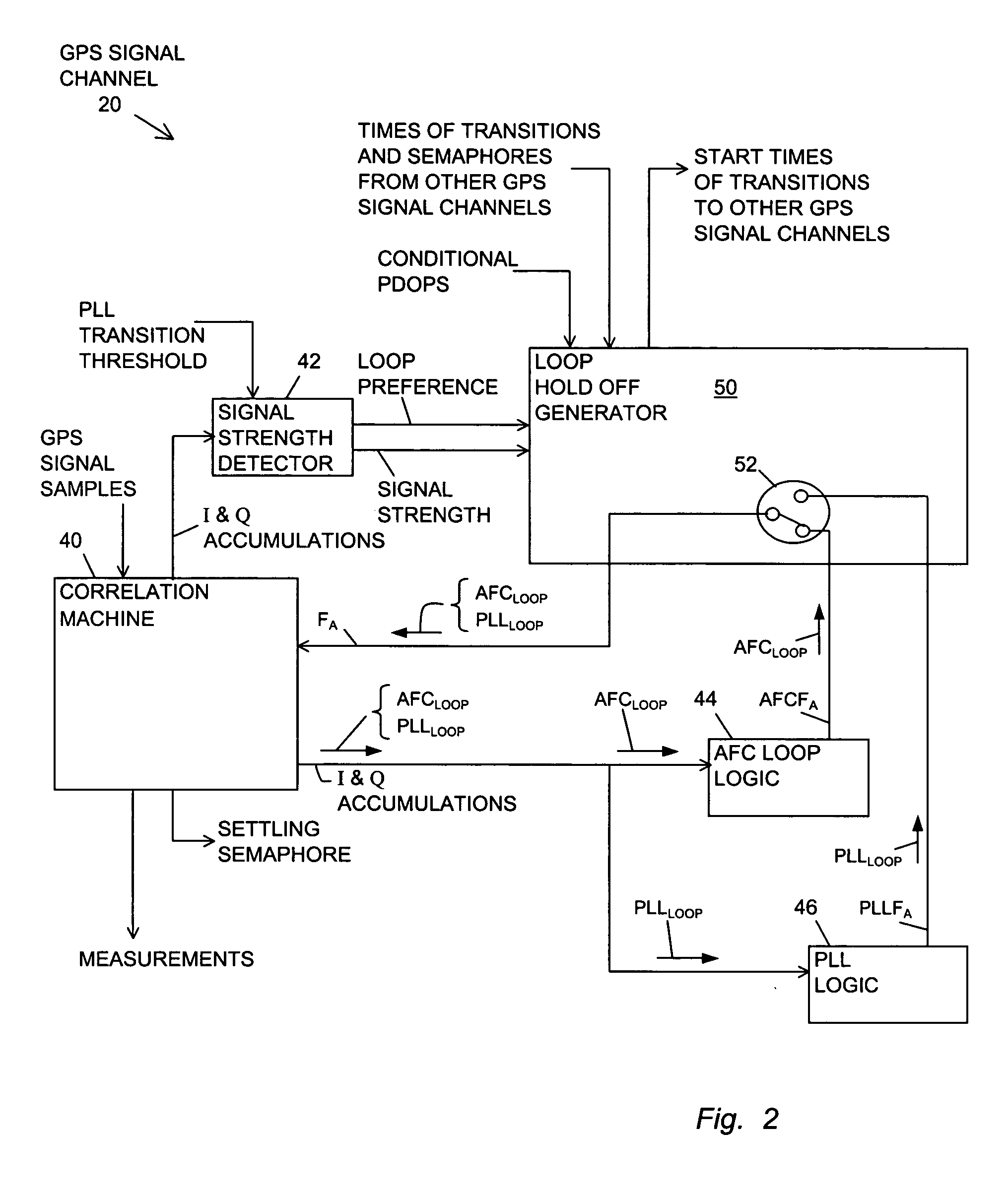
[0065]FIG. 9 is a block diagram of a loop hold-off generator 150 of the present invention. The loop hold off generator 150 performs a simi...


PUM


Abstract

A global navigation satellite system (GNSS) receiver using phase lock loops for strong GNSS signals and (AFC) loops for weak GNSS signals on a satellite-by-satellite basis. The phase lock loops or the AFC loops associated with particular GNSS satellites generate frequency feedback adjustments for tracking the carrier frequencies of the incoming GNSS signals in order to determine pseudoranges for calculating a location fix. The transition from an AFC loop to a phase lock loop is controlled for each GNSS signal depending on location quality parameters including a history of previous loop transitions, knowledge of whether a transition is in-progress, and a conditional PDOP where the pseudorange from the GNSS signal is removed from the computation of the location fix.

Description

BACKGROUND OF THE INVENTION [0001] 1. Field of the Invention [0002] The invention relates generally to global navigation satellite system (GNSS) receivers and more particularly to GNSS receivers and methods for tracking weak and strong GPS signals by switching between an AFC loop and a phase lock loop. [0003] 2. Description of the Background Art [0004] Global navigation satellite system (GNSS) receivers operate by adjusting the phase of a local replica code to the phase of a pseudorandom (PRN) code carried on an incoming GNSS signal. A global positioning system (GPS) is an example of a GNSS receiver. [0005] The local code phase in a GNSS receiver is converted to a range between the local antenna location and the location-in-space of the GNSS satellite transmitting the GNSS signal carrying that particular code. The range is termed a “pseudorange” because the range includes local receiver clock error. In the simplest case, four pseudoranges are needed for resolving the phase offset er...

Claims


Application Information

Patent Timeline
Patent Type & Authority Applications(United States)
IPC IPC(8): G01S5/14G01S19/29G01S19/37
CPCG01S19/29G01S19/37
Inventor RAO, KRISHNARANJAN S.BEST, GREGORY C.SANDERS, JEFFREY D.
Owner TRIMBLE NAVIGATION LTD
Why Eureka
Try Eureka