Horizontal in-well treatment system and source area bypass system and method for groundwater remediation

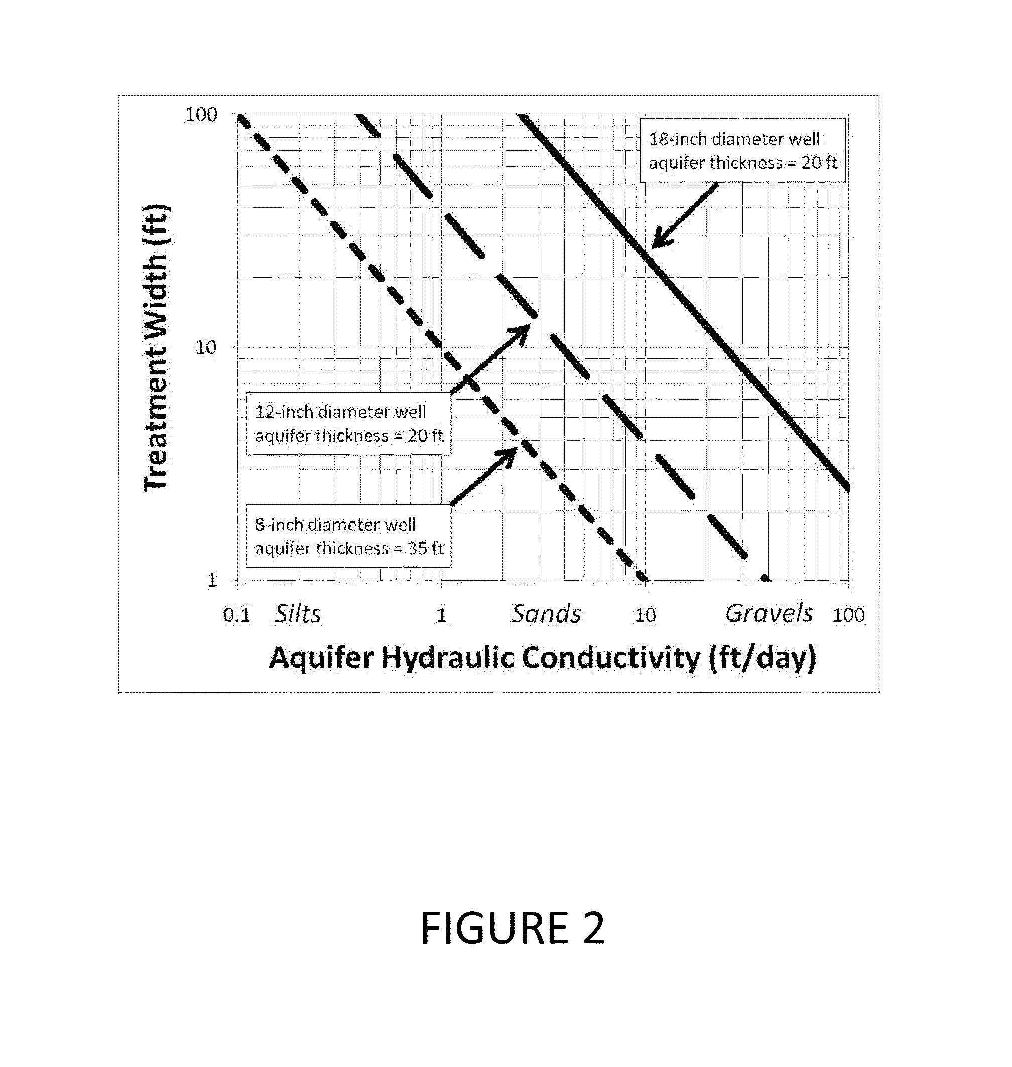
a treatment system and bypass technology, applied in the field of horizontal inwell treatment system and source area bypass system and groundwater remediation method, can solve the problems of inability to achieve ideal candidate sites with low natural bulk hydraulic conductivity values (typically less than approximately 5 ft/day), inconvenient maintenance, and inability to meet the requirements of recurring and cumulative energy requirements and carbon footprint, and achieves the effect of reducing recurring material use and waste generation, enhancing performance, and reducing the cost o

Active Publication Date: 2013-12-03
ARCADIS U S
View PDF3 Cites 1 Cited by
  • Summary
  • Abstract
  • Description
  • Claims
  • Application Information

AI Technical Summary

Benefits of technology

[0018]In another embodiment of the invention, a source area bypass (SAB) system comprises one or more horizontal wells, constructed in a manner to allow un-impacted or cleaner groundwater to bypass a non-aqueous phase liquid (NAPL) zone or high-concentration source area of contamination and discharge down-gradient of the contamination area. Reactive media may or may not be used in a SAB system. In some configurations, groundwater pumps may be installed to enhance performance.
[0019]The HRX well system compares favorably in sustainability analyses relative to conventional remedial approaches. Because the HRX well system operates passively in situ, recurring and cumulative energy requirements and carbon footprint are believed to be much lower compared to many other remedial alternatives. Additionally, recurring material use and waste generation are believed to be much lower, and the life-cycle water consumption would be essentially zero. Because the system is in situ and therefore requires minimal above-ground infrastructure and surface access, retention and potential enhancement and incorporation of natural resources would be high. Relative safety would be high due to the reduced number of wells required (i.e., fewer drilling locations and less drilling time), minimal above-ground construction (and associated electrical requirements and heavy equipment activity), absence of electrical or other power requirements, and the reduced site activities and operation and maintenance visits. Finally, the life-cycle costs for a HRX well system would be substantially lower than most conventional alternative remedial strategies, particularly if remedial performance goals are focused on mitigating risk through reducing contaminant mass flux and discharge. Although approximate, HRX well technology is a sustainable and green remedial approach.

Problems solved by technology

In most cases, sites with low natural bulk hydraulic conductivity values (typically less than approximately 5 ft / day) are not considered ideal candidate sites for injected liquid-reagent-based in situ remedial strategies.
This is primarily because at these sites, injection times necessary to deliver adequate reagent volume under non-fracturing pressures are prohibitively long.
Injected reagent-based strategies are also challenged by the difficulty in delivering and distributing the reagent to the target zones within the plume.
However, an important implication of this concept is that conventional batch-volume injection methods will not be technically-appropriate or cost-effective for large plumes.
Finally, despite the widespread success of injected remedial reagent approaches for select contaminants, there still remain a large number of contaminants (e.g., select metals and radionuclides, polycyclic aromatic hydrocarbons, explosives and energetics, chlorides) that are not treatable, or their treatment is relatively undemonstrated by currently-available liquid-based remedial agents.
Additionally, while many soluble substrates (i.e., lactate, molasses and other organic carbon sources) are ideally suited to an injection approach, they are not ideal with respect to reaction rates since their effectiveness in contaminant destruction relies on promoting microbiological activity.
While theoretically plausible, the concept is not practical or cost-effective for most sites because the treatment widths for individual reactive wells are very small (roughly twice the well diameter) due to negligible flow-focusing, and therefore, many wells would be necessary to achieve a system width appropriate for typical plumes.
Furthermore, the in-well residence times for these systems are very short (a few hours to a few days) and this may not be long enough to achieve treatment of some contaminants.
However, this approach at applying solids in the treatment of plumes is not ideal: trenching is an expensive and difficult operation, reactive solid media have limited life-span and rehabilitation of the barrier is often not feasible, and often large portions of a plume cannot be treated because of limitations on trenching at a site.
Other reactive media are also not available for use in trenches, such as ion-exchange resins and granular activated carbon (solids used successfully in ex-situ applications) due to the media cost and the need for large quantities to fill a trench.
Some limited work has been performed to evaluate the hydraulic performance of trench-based PRB systems oriented at non-orthogonal angles.
Very recently, Hudak conducted some limited modeling of hypothetical reactive media-filled fully-penetrating PRBs used to treat the leading edge of synthetic plumes.
While further work is needed to evaluate the potential benefits and the limitations of alternative orientations, there are important cost and implementability limitations associated with conventional PRBs.
Trenching is relatively expensive as costs are particularly sensitive to trench depth.
Further, there are challenges associated with achieving adequate contaminant residence times for conventional orientations, and the hydraulic performance of many existing systems has been impacted by clogging and reduction in permeability, which can result in undesirable alteration of the flowfield and even plume spreading and bypass around the PRB.
Lastly, access issues such as buildings and utilities may limit the use of trenches.

Method used


Image

  • Horizontal in-well treatment system and source area bypass system and method for groundwater remediation
  • Horizontal in-well treatment system and source area bypass system and method for groundwater remediation
  • Horizontal in-well treatment system and source area bypass system and method for groundwater remediation

Examples


Embodiment Construction

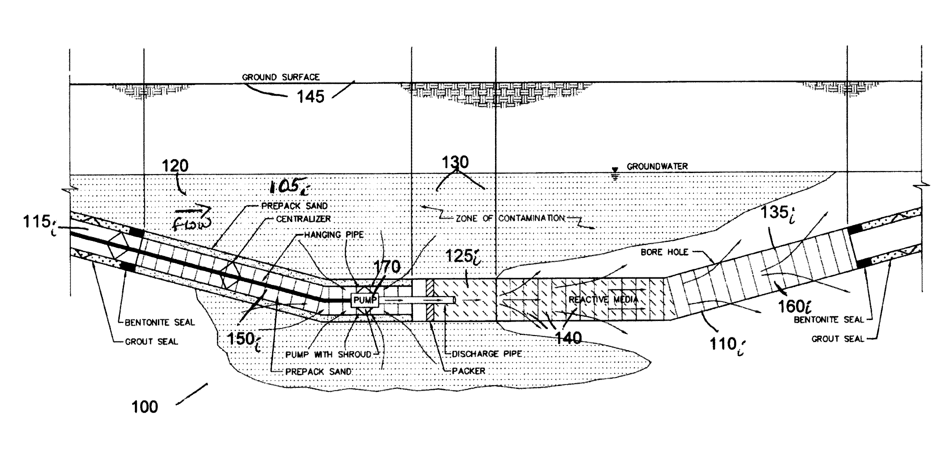
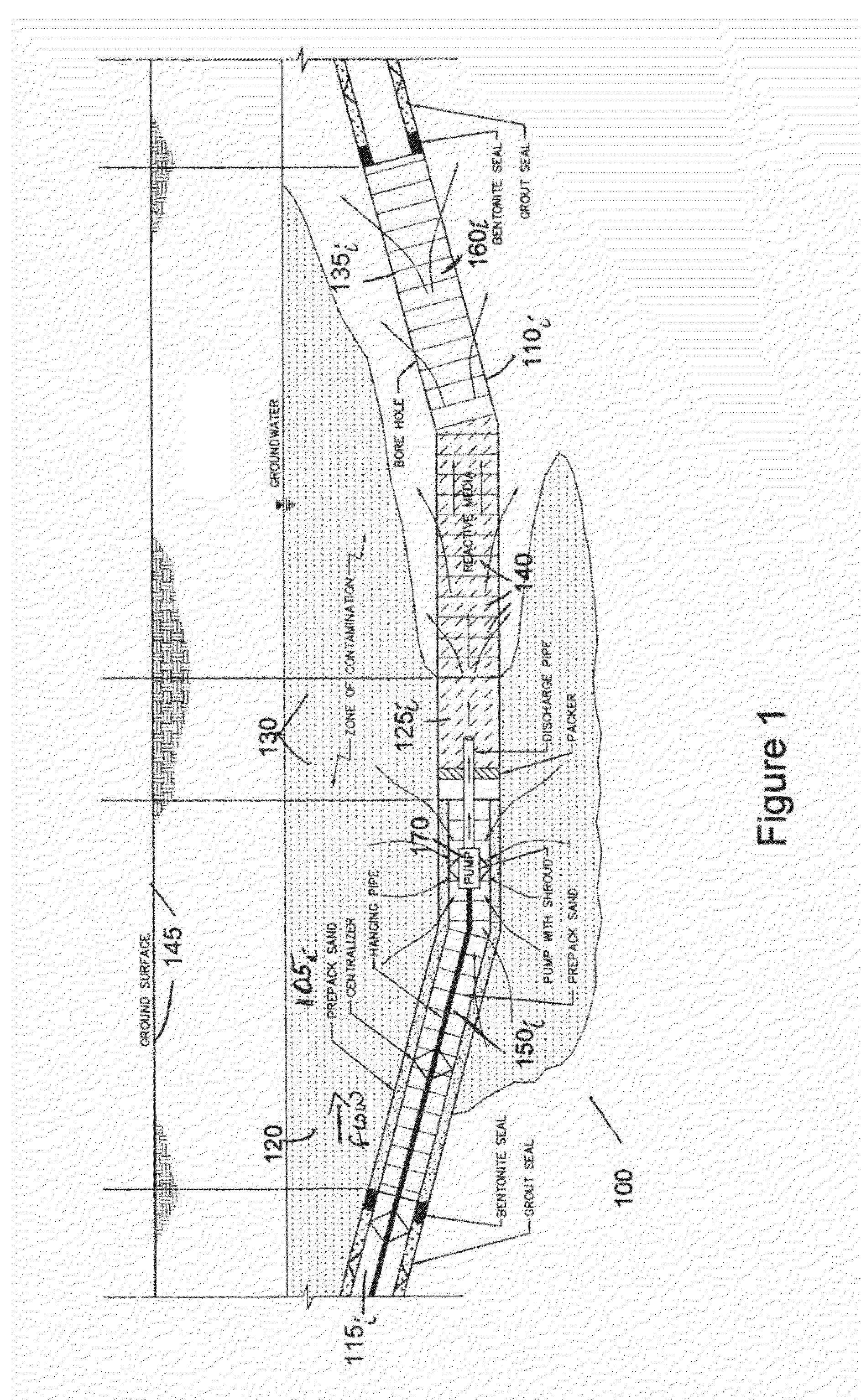
[0034]The invention relates to a horizontal treatment (HRX) well system (also known as a horizontal in-well treatment (HIT) remediation system) comprising horizontal wells that are installed within plumes of contaminated groundwater and oriented in the general direction of groundwater flow. Each well is filled with reactive treatment media (comprising, e.g., iron, granular activated carbon, zeolite). A flow-focusing phenomenon is created by the high in-well hydraulic conductivity of the well and engineered reactive media relative to the surrounding aquifer hydraulic conductivity that passively draws impacted groundwater into the horizontal wells through a screen disposed substantially at the up-gradient portion of each well such that impacted groundwater is treated as it flows through the horizontal well. Treated groundwater then exits each horizontal well through a screen disposed substantially along the down-gradient section of the well.

[0035]According to one embodiment, the inven...


PUM


Abstract

The application relates to a sustainable and green remedial approach for in situ remediation. The system and method use directionally drilled horizontal wells filled with granular reactive media generally installed in the direction of groundwater flow for groundwater remediation. “Flow-focusing” behavior is leveraged to capture and passively treat proportionally large volumes of groundwater in situ. The system and method perform well in low hydraulic conductivity environments. Reactive media are selected according to the contaminants to be treated and site characteristics The application further relates to a source area bypass system comprising one or more horizontal wells, constructed in a manner to allow unimpacted or cleaner groundwater to bypass a nonaqueous phase liquid zone or high-concentration source area of contamination and discharge downgradient. Reactive media may or may not be used in a source area bypass system. In some configurations, groundwater pumps may be installed to enhance performance.

Description

FIELD OF THE INVENTION[0001]The application relates to a sustainable and green remedial approach for in situ remediation. The system and method use directionally drilled horizontal wells filled with granular reactive media generally installed in the direction of groundwater flow for groundwater remediation. “Flow-focusing” behavior is leveraged to capture and passively treat proportionally large volumes of groundwater in situ. The system and method perform well in low hydraulic conductivity environments where the success of other in situ remediation methods is controlled by aquifer injectability. Reactive media are selected according to the contaminants to be treated and site characteristics. Energy conservation and other considerations result in considerable cost savings compared to current in situ remediation systems. According to another embodiment of the invention, a source area bypass comprises one or more horizontal wells, constructed in a manner to allow unimpacted or cleaner...

Claims


Application Information

Patent Timeline
Patent Type & Authority Patents(United States)
IPC IPC(8): E21B43/22B09C1/10
CPCB09C1/002B09C1/08
Inventor DIVINE, CRAIG E.LEONE, GASTONGILLOW, JEFFERY B.ROTH, TRACYBRENTON, HARRYSPURLIN, MATTHEW S.
Owner ARCADIS U S
Why Eureka
Try Eureka