Dual scara arm

a technology of scara arm and substrate, which is applied in the direction of mechanical control devices, instruments, process and machine control, etc., can solve the problems of affecting the overall footprint of the transport apparatus and the longer swap time of the conventional transport apparatus

Active Publication Date: 2006-05-11
BOOKS AUTOMATION US LLC
View PDF8 Cites 107 Cited by
  • Summary
  • Abstract
  • Description
  • Claims
  • Application Information

AI Technical Summary

Problems solved by technology

As may be realized, there are constraints that operate against these efforts to improve fab efficiency that intrinsically arise from the fabrication system itself.
This in turn defines this extension of the transport apparatus, to transport wafers to the different tool modules, which in turn impacts the overall footprint of the transport apparatus.
Though

Method used


Image

  • Dual scara arm
  • Dual scara arm
  • Dual scara arm

Examples


Embodiment Construction

(s)

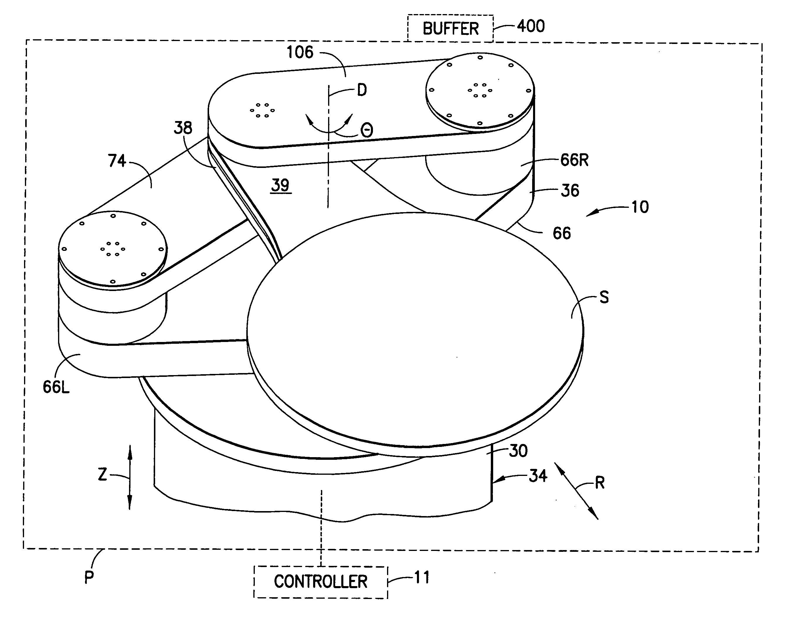
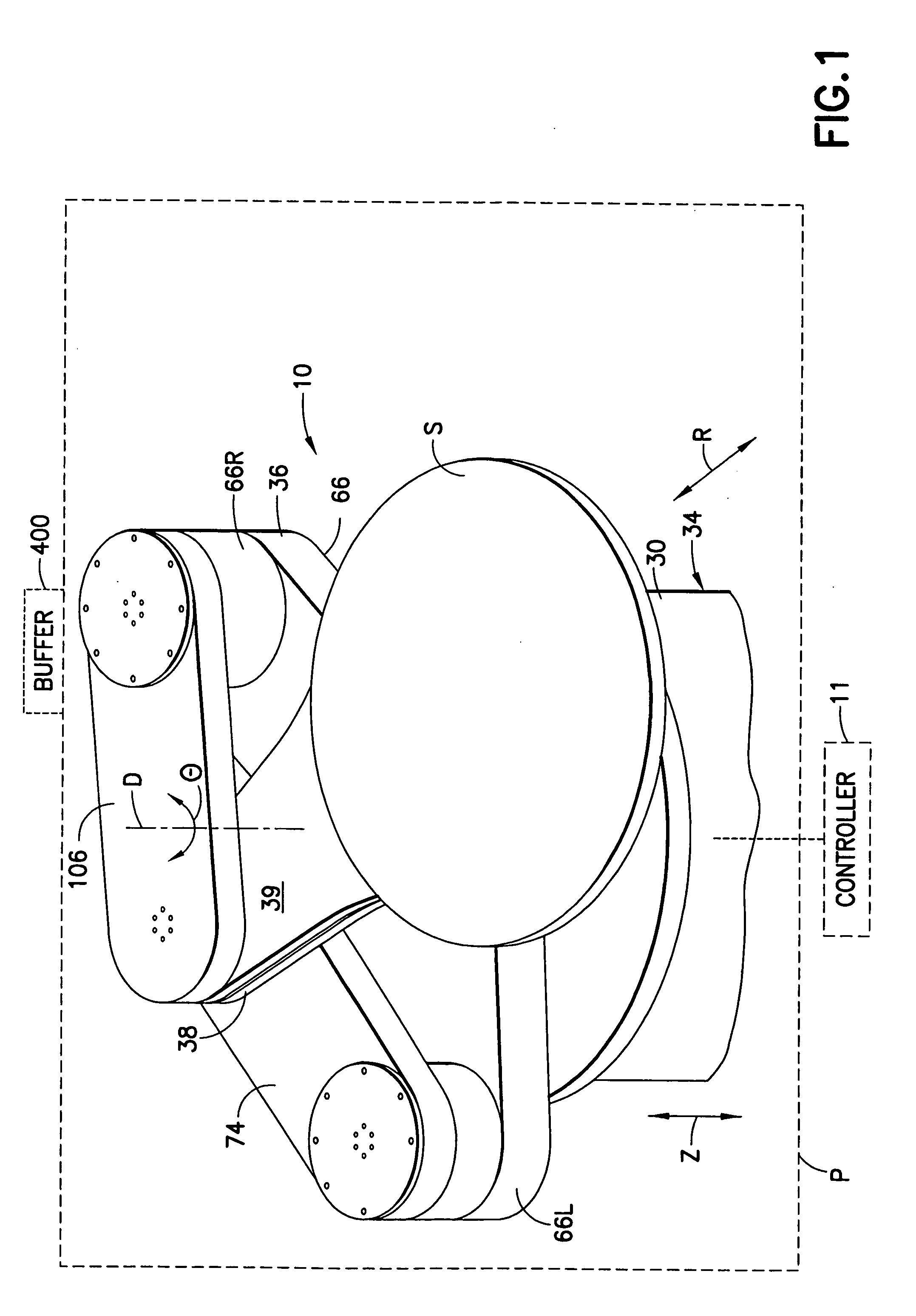
[0022] Referring to FIG. 1, a perspective view is provided of a substrate transport apparatus 10 incorporating features of the present invention, in accordance with one exemplary embodiment. Although the present invention will be described with reference to the embodiment shown in the drawings, it should be understood that the present invention can be embodied in many alternate forms of embodiments. In addition, any suitable size, shape or type of elements or materials could be used.

[0023] In FIG. 1, the substrate transport apparatus 10 is shown being used to transport semiconductor wafers S, such as 200 mm or 300 mm wafers, for example purposes. The transport apparatus, in accordance with the exemplary embodiments described herein, however may be suitably configured to handle any desired flat workpiece items including the 200 mm or 300 mm semiconductor wafers (already mentioned), semiconductor packaging substrates (such as high density interconnects HOI), semiconductor processi...


PUM


Abstract

A substrate transport apparatus having a drive section and a scara arm operably connected to the drive section to move the scara arm. The scara arm has an upper arm and at least one forearm. The forearm is movably mounted to the upper arm and capable of holding a substrate thereon. The upper arm is substantially rigid and is adjustable for changing a predetermined dimension of the upper arm.

Description

CROSS-REFERENCE TO RELATED APPLICATION(S) [0001] This application claims the benefit of U.S. Provisional Application No. 60 / 578,571 filed Jun. 9, 2004 which is incorporated by reference herein in its entirety.BACKGROUND [0002] 1. Field of the Invention [0003] The present invention relates to a substrate transport apparatus. [0004] 2. Brief Description of Related Developments [0005] The continuous demand by consumers for ever cheaper electronic devices has maintained pressure on manufacturers of the device to improve efficiency. Indeed, in the current market place, many of the devices, and to a much greater extent in the electronic and semiconductor components used in the devices, have become commodities. The desire of manufacturers of electronic and semiconductor device to increase efficiency manifests itself at all levels, but is of special significance in the design, construction, and operation of fabrication facilities or fabs. One unit by which to measure the efficiency of a giv...

Claims


Application Information

Patent Timeline
IPC IPC(8): B66C23/00B25J9/04
CPCB25J9/042H01L21/67742Y10T74/20305H01L21/677H01L21/68707Y10S901/15Y10S901/27B66C23/00B25J9/043B25J18/00
Inventor PIETRANTONIO, ANTONIO F.CHESNA, ANTHONYALMALI, HAKANGILCHRIST, ULYSSES
Owner BOOKS AUTOMATION US LLC
Why Eureka
Try Eureka