Extraluminal balloon dissection

a balloon and balloon technology, applied in the field of extraluminal balloon dissection, can solve the problems of not being particularly well suited to surgical procedures on elongated structures, and achieve the effect of shortening the pre-deployment length and shortening the balloon

a balloon and balloon technology, applied in the field of extraluminal balloon dissection, can solve the problems of not being particularly well suited to surgical procedures on elongated structures, and achieve the effect of shortening the pre-deployment length and shortening the balloon

US20060106414A1Inactive Publication Date: 2006-05-18TYCO HEALTHCARE GRP LP +1

Image

  • Extraluminal balloon dissection
  • Extraluminal balloon dissection
  • Extraluminal balloon dissection

Examples


Embodiment Construction

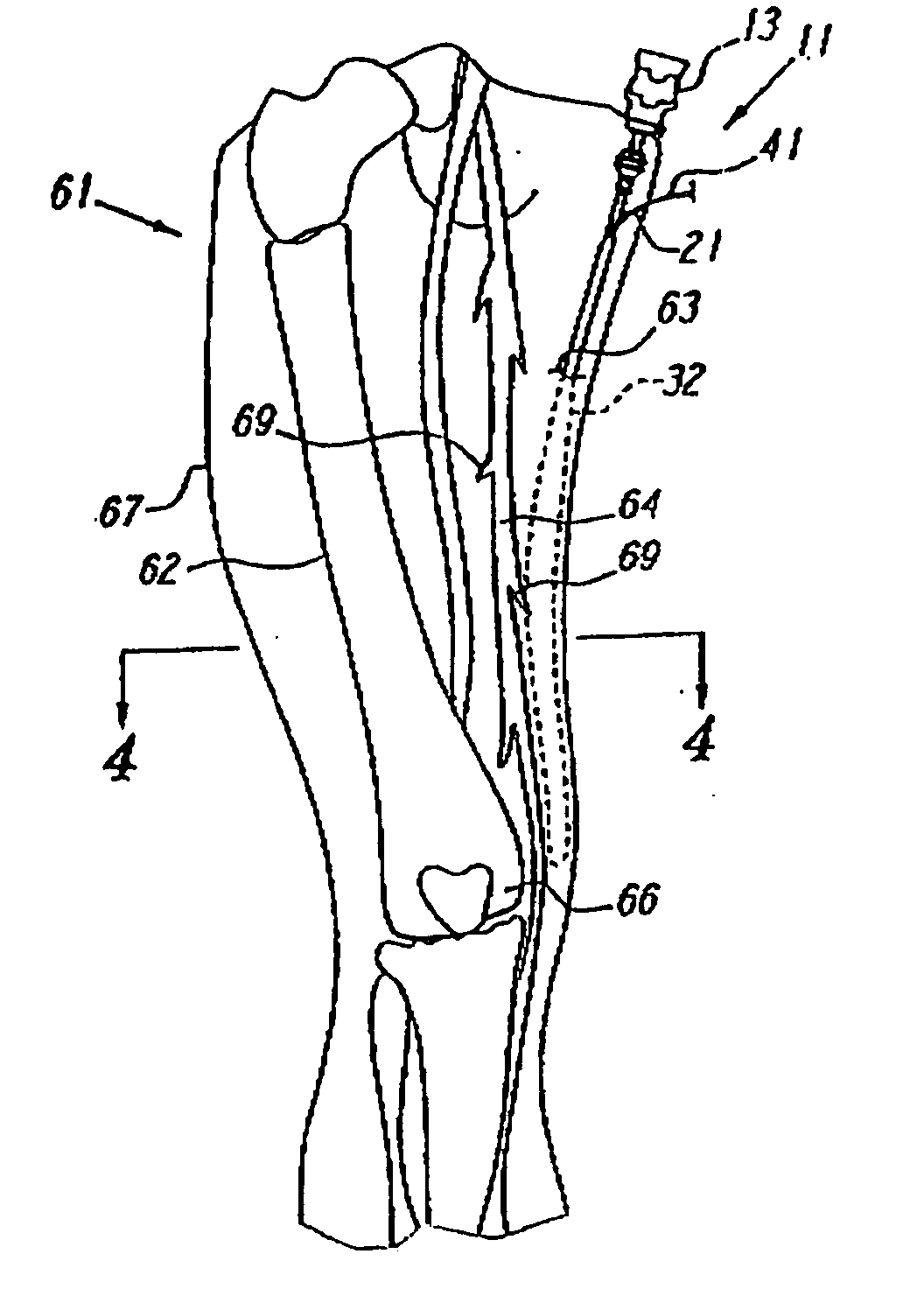
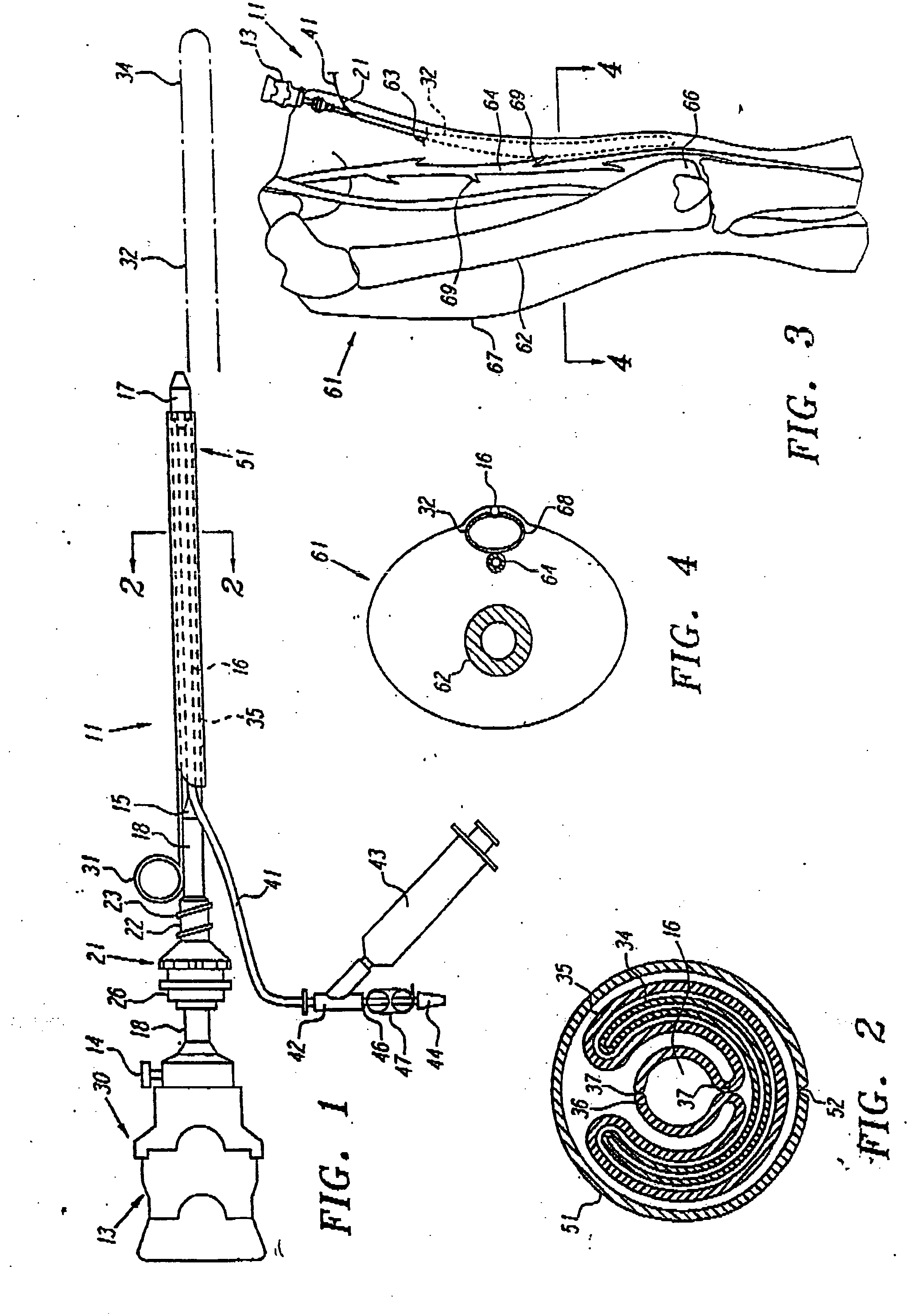
[0032] In the exemplary embodiment illustrated in FIG. 1, an extraluminal balloon dissection apparatus 11 includes a tunneling shaft assembly 30 substantially similar to the tunneling shaft assembly disclosed in application Ser. No. 07 / 893,988, an elongate balloon 32, a skin seal 21, and a removable balloon cover 51. The tunneling shaft assembly 30 has a piece handle 13. Alternatively, a hollow tube having either a one or two piece handle construction as disclosed in Ser. No. 08 / 570,766 may be utilized with an elongate balloon according to the invention. The three-piece handle 13 includes a cannula 18, an obturator 15, and a tunneling shaft 16, each of which extend from a different section of the handle 13. The tunneling shaft 16 extends through a bore in the obturator 15, and the obturator 15 extends through the cannula 18. The tunneling shaft 16 may have an olive-shaped, or other blunt shaped obturator 17 mounted on its distal end to provide a blunt distal end for tunneling. A ski...


PUM


Abstract

The present invention provides balloon dissection apparatus and methods of use in which an elongate balloon is utilized to dissect along a region that follows a naturally existing path alongside a vessel or structure, such as an entry, a vein, a lymphatic vessel, the traches, the esophagus, or even a nerve bundle.

Description

[0001] This application is a continuation on of co-pending U.S. application Ser. No. 09 / 039,548; filed on Mar. 16, 1998; which is a continuation of U.S. pending application Ser. No. 08 / 824,676, filed on Mar. 26, 1997, which is a continuation of U.S. application Ser. No. 08 / 631,221, filed on Jun. 29, 1994, now U.S. Pat. No. 5,690,668, which is a continuation-in-part of U.S. application Ser. No. 08 / 267,484, filed on Jun. 29, 1994, now U.S. Pat. No. 5,601,589, the disclosures of which hereby incorporated by reference in their entirety.FIELD OF THE INVENTION [0002] The present invention relates generally to the field of extraluminal balloon dissection. More particularly, the present invention relates to vascular methods and apparatus which can used for creating an anatomic working space alongside an elongate structure, such as a vessel or nerve, for example. BACKGROUND OF THE INVENTION [0003] In commonly assigned copending application Ser. No. 07 / 893,988, filed on Jun. 2, 1992, apparatu...

Claims


Application Information

Patent Timeline
18 May 2006
Publication
US20060106414A1
IPC
A61M29/00; A61M25/00; A61B1/32; A61B17/00; A61B17/22; A61B17/32; A61B17/34; A61B19/00; A61M25/01; A61M29/02
CPC
A61B17/00008; A61B17/0218; A61B17/3431; A61B19/5212; A61B2017/00557; A61B2017/22061; A61B2017/22062; A61B2017/320044
Inventors
FOGARTY, THOMAS J.; HERMANN, GEORGE D.