Expandable perfusion balloon

a balloon and balloon technology, applied in balloon catheters, medical science, surgery, etc., can solve the problems of reducing the diameter and length of inner tubes, reducing the oxygen delivery to the brain, the heart, and other tissues of the body, and reducing so as to improve the sizing of such lumens and the effect of durability

Inactive Publication Date: 2014-08-19
THIELEN JOSEPH MICHAEL +1
View PDF8 Cites 6 Cited by
  • Summary
  • Abstract
  • Description
  • Claims
  • Application Information

AI Technical Summary

Benefits of technology

[0008]The angle of the braided filaments found in the balloon is chosen such that upon inflation of the balloon, the inflation pressure causes the balloon to expand in diameter while the balloon length is forced to reduce due to the presence of the braid. The lower the angle of the braided filaments with respect to the axis of the balloon the greater the force acting to shorten the balloon. Since the balloon is attached to the inner tubing, the expansion force from the balloon will act to shorten the length of the inner tubing. The braided filaments of the balloon therefore are structural in the respect that they cannot stretch during the perfusion balloon inflation and must instead transfer the expansion force of the balloon wall into a force that reduces it in length.
[0019]In a yet further embodiment, a drug such as Taxol or Sirolimus can be applied to the outside of the perfusion balloon prior to dilation against the vessel wall or the diseased leaflets of the aortic valve. The increased time for exposure of the tissue to the drug while the perfusion balloon is inflated will allow the drug to more effectively penetrate into the tissue.

Problems solved by technology

For the case of coronary angioplasty, blood flow to the distal coronary tissue bed can be temporarily halted during balloon inflation resulting in lack of proper oxygen delivery to the myocardium.
For the case of aortic valvuloplasty, blood flow from the left ventricle of the heart is temporarily blocked by the inflated balloon resulting in a reduced oxygen delivery to the brain, the heart, and other tissues of the body.
As the inner tubing is exposed to the inflation pressure, this generates a force that generally creates a tendency for the inner tubing to reduce in diameter and increase in length; however, since the surface area of the inner tubing is smaller than the balloon, the inner tubing and the balloon will both shorten in length due to the inflation pressure and the perfusion balloon will increase in diameter.
The result is that inflation of the perfusion balloon results in shortening of the balloon and tubing length and an increase in diameter of both the balloon and inner tubing.

Method used


Image

  • Expandable perfusion balloon
  • Expandable perfusion balloon
  • Expandable perfusion balloon

Examples


Embodiment Construction

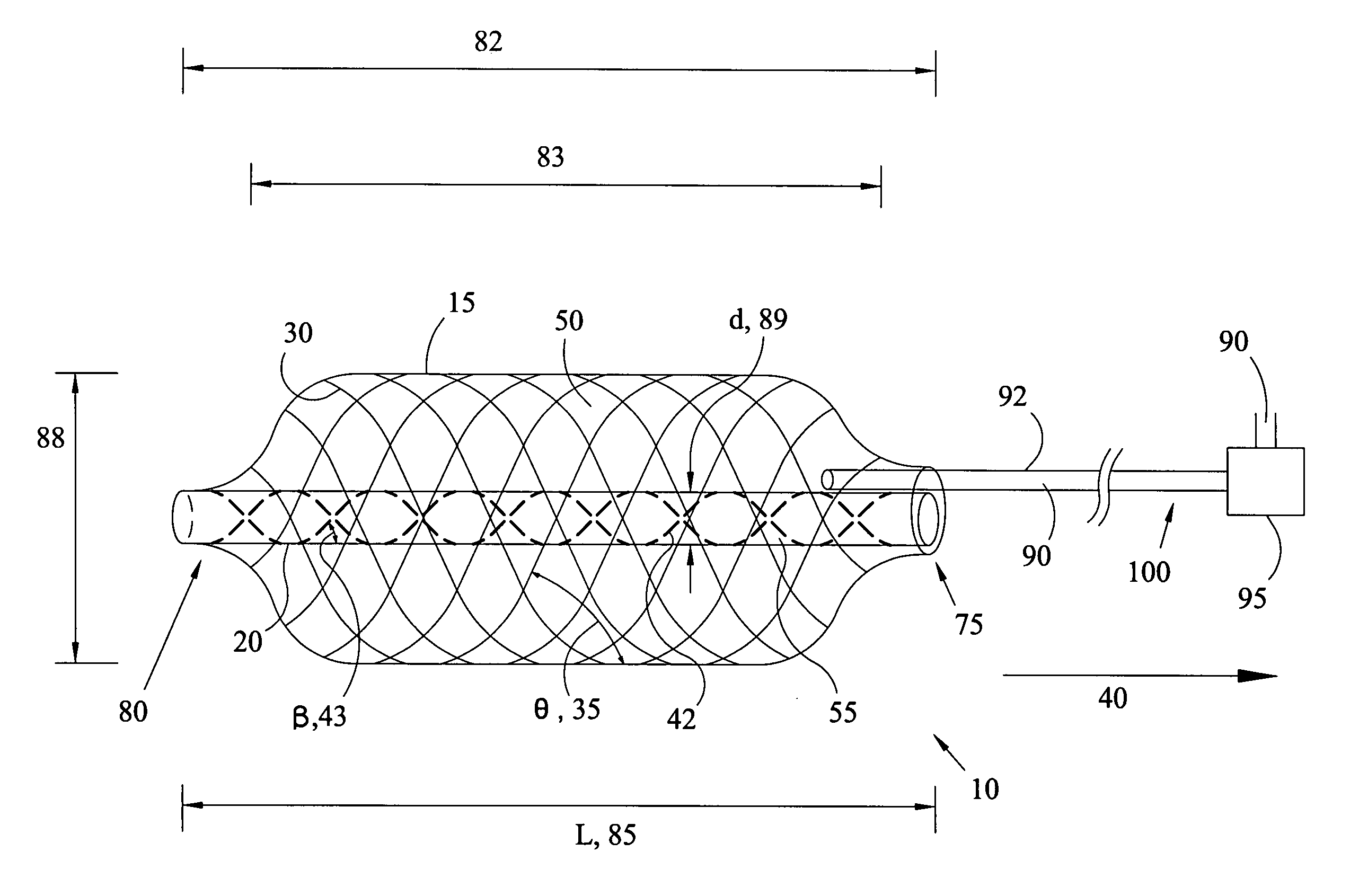
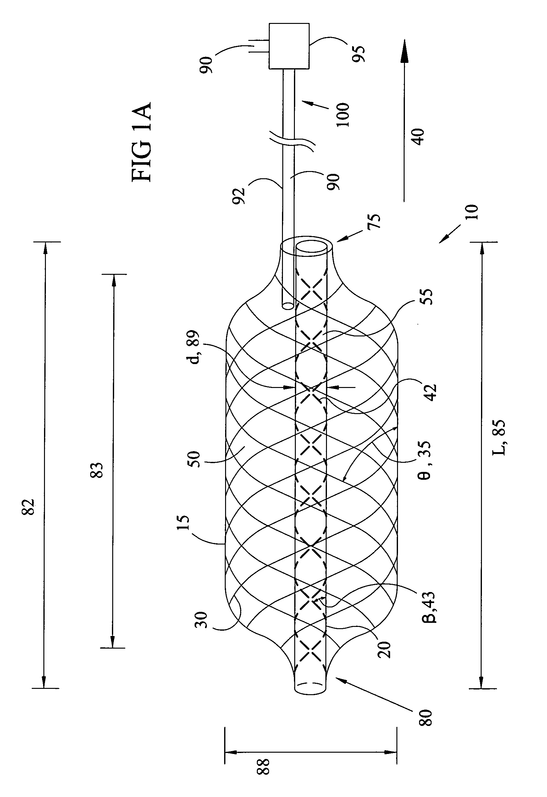
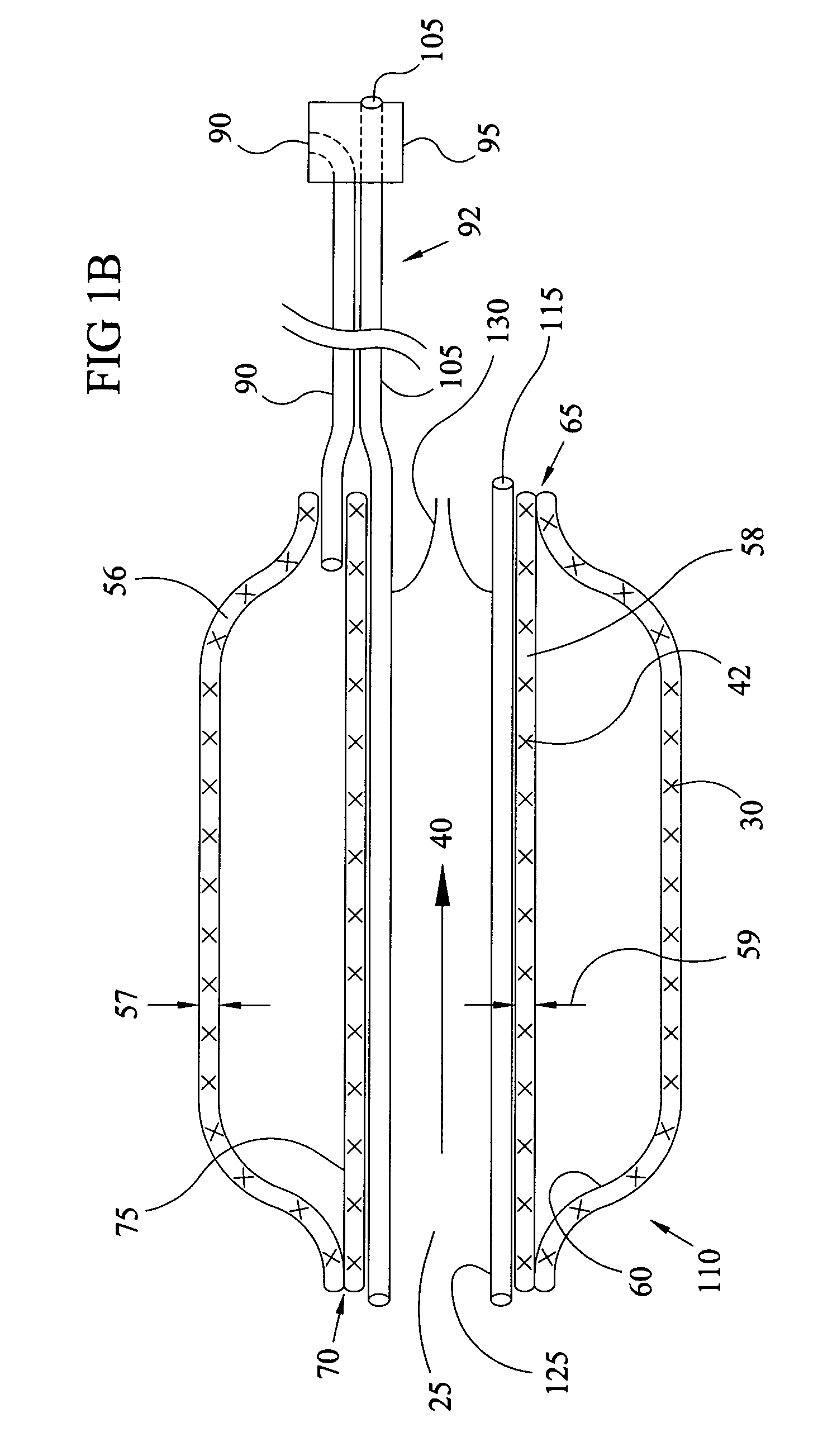
[0037]The present invention is an interventional catheter having a perfusion balloon (10) located at or near its distal end. The perfusion balloon (10) is comprised of an outer balloon (15) and an inner tubing (20) that provides one embodiment of the perfusion lumen (25) as shown in FIGS. 1A and 1B. In this embodiment, the outer balloon or outer tubing (15) is braided with balloon filaments (30) at a balloon filament angle (35), Theta (θ), with respect to the axial direction (40) and the inner tubing (20) has braided tube fibers (42) braided at tube fiber angle (43), Beta, (β) with respect to the axial direction (40). The inner tubing (20) is positioned within the outer balloon (15) forming an annular space (45) located between the outer tubing or outer balloon (15) and the inner tubing (20). The outer balloon filaments can be braided as shown in FIGS. 1A-1B however it is understood that any angled filaments formed from a spiral or machined tubing can also be used to form the perfus...


PUM


Abstract

A balloon catheter for dilation of stenotic tissue within a tubular member of the body such as a blood vessel provides fluid flow such as blood flow through the balloon while it is being inflated and after it has been inflated. For valvuloplasty applications or for predilitation prior to a TAVI procedure the balloon is placed across the stenotic aortic valve leaflets and inflated to push the leaflets aside to create a greater blood flow area or allow improved subsequent passage of the large TAVI catheter across the stenotic aortic valve leaflets. As the balloon is inflated in diameter, it is required to reduce in length; this length reduction causes a braided inner tubing to also reduce in length. The braided inner tube is thereby required it to increase in diameter during the balloon inflation and create a suitably large blood flow path through the inner tubing. The continuous perfusion through the inner tubing of the balloon allows greater balloon inflation times, improved valvular dilation, and obviates the need for rapid pacing during the valvuloplasty procedure.

Description

CROSS REFERENCE TO RELATED APPLICATIONS[0001]This patent application claims priority to U.S. Provisional Application Ser. No. 61 / 343,244 entitled Braided Perfusion Balloon by Joseph M. Thielen filed 26 Apr. 2010, and priority to U.S. Provisional Application Ser. No. 61 / 460,953 entitled Expandable Perfusion Balloon by Joseph M. Thielen and William J. Drasler filed 10 Jan. 2011, both of which provisional applications are hereby incorporated herein by reference in their entirety.FIELD OF THE INVENTION[0002]This invention relates to an interventional catheter that is placed into a lumen of the body in a smaller diameter configuration and is expanded to a larger diameter configuration in apposition with the lumen while maintaining passage for flow of fluid through the lumen.BACKGROUND OF THE INVENTION[0003]Providing expansion or enlargement to blood vessels and other tubular organs of the body including coronary arteries and veins, peripheral arteries and veins, the aorta, the aortic roo...

Claims


Application Information

Patent Timeline
Patent Type & Authority Patents(United States)
IPC IPC(8): A61M37/00A61M29/00A61M31/00A61F2/958A61M25/10
CPCA61M2025/1095A61M2025/1081A61M2025/1084A61M25/104A61M2025/105A61M2025/1093A61M2025/1075A61B17/2202A61B2017/22084A61B2017/22098
Inventor THIELEN, JOSEPH MICHAELDRASLER, WILLIAM JOSEPH
Owner THIELEN JOSEPH MICHAEL
Why Eureka
Try Eureka