
Cooperative collision mitigation

Inactive Publication Date: 2006-05-18
GM GLOBAL TECH OPERATIONS LLC
View PDF32 Cites 56 Cited by
  • Summary
  • Abstract
  • Description
  • Claims
  • Application Information

AI Technical Summary

Problems solved by technology

A short coming of such a system is that a prediction of the severity of an imminent collision based only upon the relative position and velocity of the object, without identifying the nature of the object itself, can be inaccurate.

Method used


Image

  • Cooperative collision mitigation
  • Cooperative collision mitigation
  • Cooperative collision mitigation

Examples


Embodiment Construction

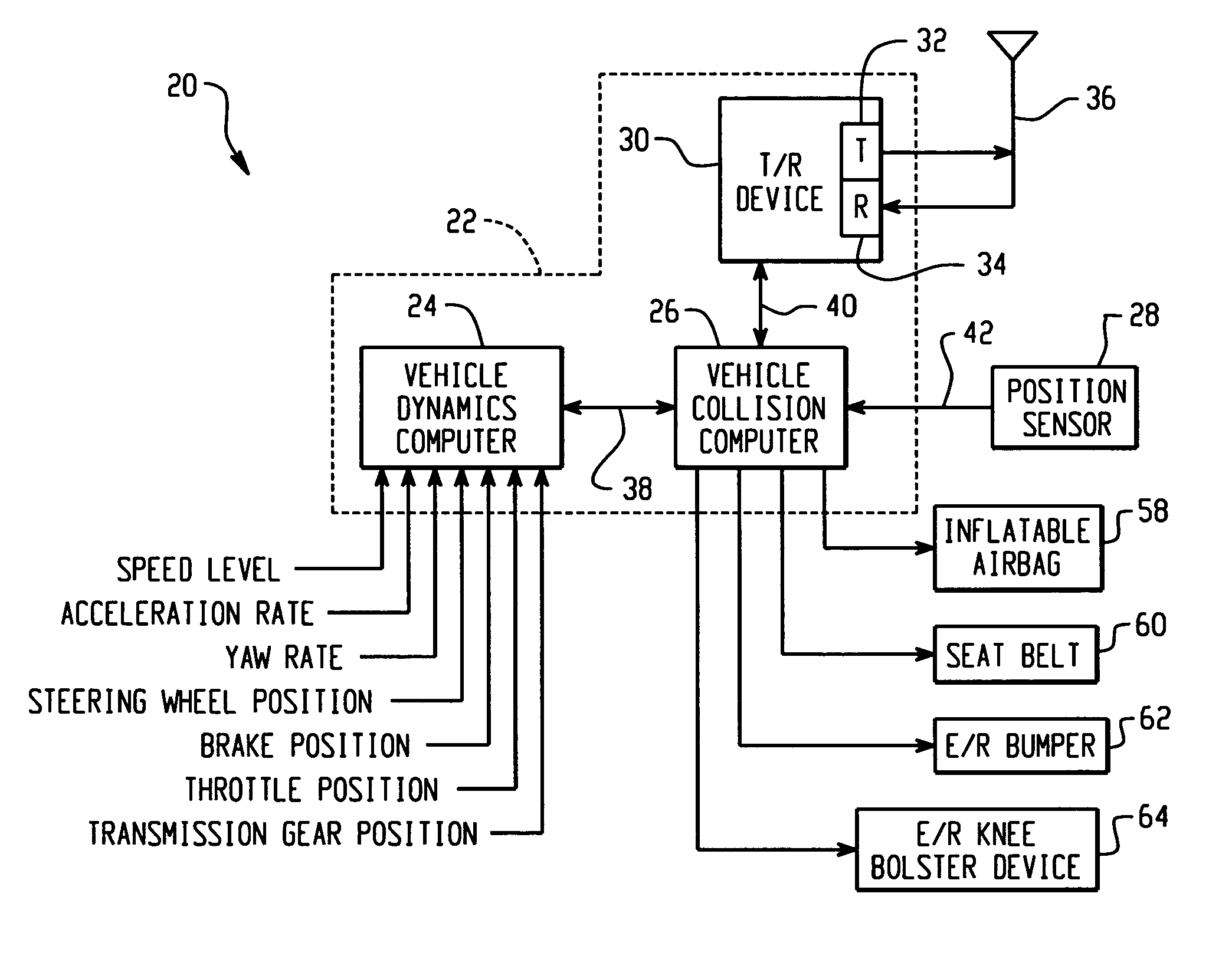
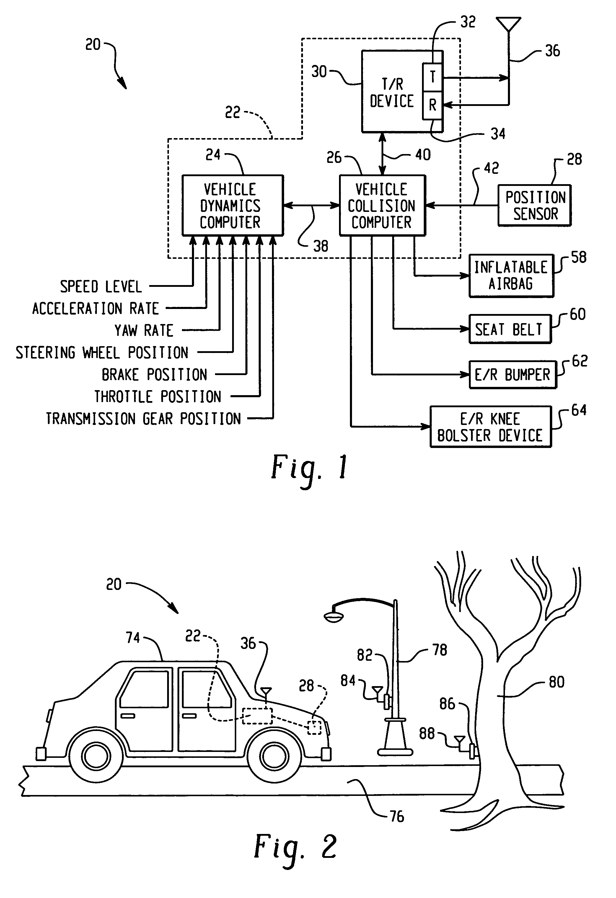
[0018] Exemplary embodiments of the present invention provide a method and system for deploying responsive devices in a vehicle, such as an automobile, in anticipation of a potential collision with an object. The type of object may include, for example, a large tree, a small tree, a mailbox, a sign, a fire hydrant, a post, a pole, a fence, a guardrail, a building structure, or another vehicle. In deploying vehicle responsive devices, the present invention anticipates an imminent or nearly imminent potential collision with an object so that vehicle responsive devices may be activated, deployed, or pre-armed. In addition, the nature, or type, of the object may be identified so that potential collision severity can be predicted and so that individual vehicle responsive devices can be selectively deployed based on predicted collision severity.

[0019]FIG. 1 is a block diagram of a basic hardware system 20 for deploying responsive devices in a vehicle in anticipation of a collision with a...


PUM


Abstract

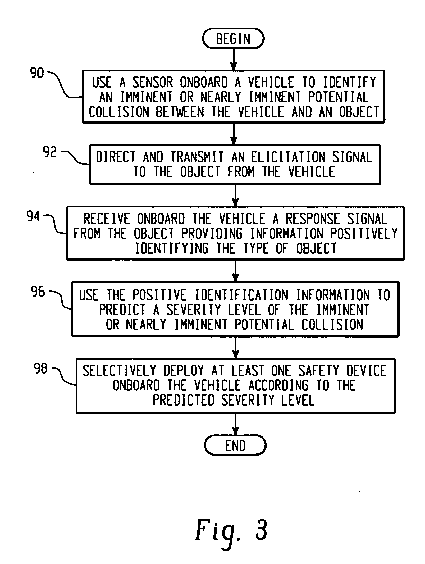
A method of predicting severity of a potential collision of a vehicle and an object. The method includes determining a probability of the potential collision. An elicitation signal is directed and transmitted to the object from the vehicle when the probability of the potential collision is greater than a threshold value. A response signal is received onboard the vehicle from a device situated on the object in response to the elicitation signal. The response signal includes a type associated with the object. A severity level of the potential collision is predicted based on the type.

Description

TECHNICAL FIELD [0001] The present invention relates to features in a vehicle for identifying objects and, more particularly, to a system for positively identifying the type of an object, assessing the relationship between the object and the vehicle, and deploying vehicle responsive devices according to certain situations. BACKGROUND OF THE INVENTION [0002] Examples of typical vehicle responsive devices include inflatable air bag systems, seat belt systems with pyrotechnic pretensioners, bumper systems, knee bolster systems and the like. These systems can be resettable, meaning that deployment does not affect their continued operability, and non-resettable, meaning that once deployed, replacement is necessary. Vehicle responsive devices that require activation or deployment are generally triggered by, and thus during, an actual physical impact event itself. That is, many vehicles utilize deploy systems that include impact sensors which are sensitive to abrupt changes in vehicle iner...

Claims


Application Information

Patent Timeline
IPC IPC(8): G08G1/16
CPCB60R21/01B60R21/0132B60R21/0134B60R21/01526B60R21/01546B60R21/01516B60R21/01558G08G1/16B60R21/01512
Inventor BROWNE, ALAN L.ALTAN, OSMAN D.KRISHNAN, HARIHARANGEISLER, SCOTT P.WOOD, FRANCIS D.
Owner GM GLOBAL TECH OPERATIONS LLC
Learn More