Supplemental restraint deployment method with displacement-based deployment immunity

a technology of supplemental restraints and deployment immunity, which is applied in the direction of process and machine control, pedestrian/occupant safety arrangement, instruments, etc., can solve the problems of difficult to reliably distinguish between deployments, heuristic in nature rather than physics-based, and complicated natur

Active Publication Date: 2010-02-09
APTIV TECH LTD
View PDF22 Cites 5 Cited by
  • Summary
  • Abstract
  • Description
  • Claims
  • Application Information

AI Technical Summary

Benefits of technology

[0004]The present invention is directed to an improved deployment immunity method for a supplemental restraint where occupant displacement due to a crash event is determined and used to enable and disable deployment of supplemental restraints based on crash severity. The determined occupant displacement is compared to a first threshold calibrated to discriminate against disturbances due to rough roads and other non-crash events and a second threshold calibrated to discriminate against non-deployment crash events. Deployment of supplemental restraints based on crash severity is enabled only when the determined displacement is between the first and second thresholds effectively providing a deployment immunity gate that is not time dependent.

Problems solved by technology

While being conceptually simple, the above-described approach can be problematic in practice because it is sometimes difficult to rule out acceleration disturbances due to rough road surfaces, particularly when the deployment decision must be made in a very early stage of the crash event.
It can also be difficult to reliably distinguish between deployment crash events and non-deployment crash events, particularly since non-deployment events sometimes result in relatively high ΔV levels in the later stage of the crash event.
Many procedures and rules have been devised for overcoming these problems, but they tend to be overly complicated and heuristic in nature rather than physics-based.

Method used


Image

  • Supplemental restraint deployment method with displacement-based deployment immunity
  • Supplemental restraint deployment method with displacement-based deployment immunity
  • Supplemental restraint deployment method with displacement-based deployment immunity

Examples


Embodiment Construction

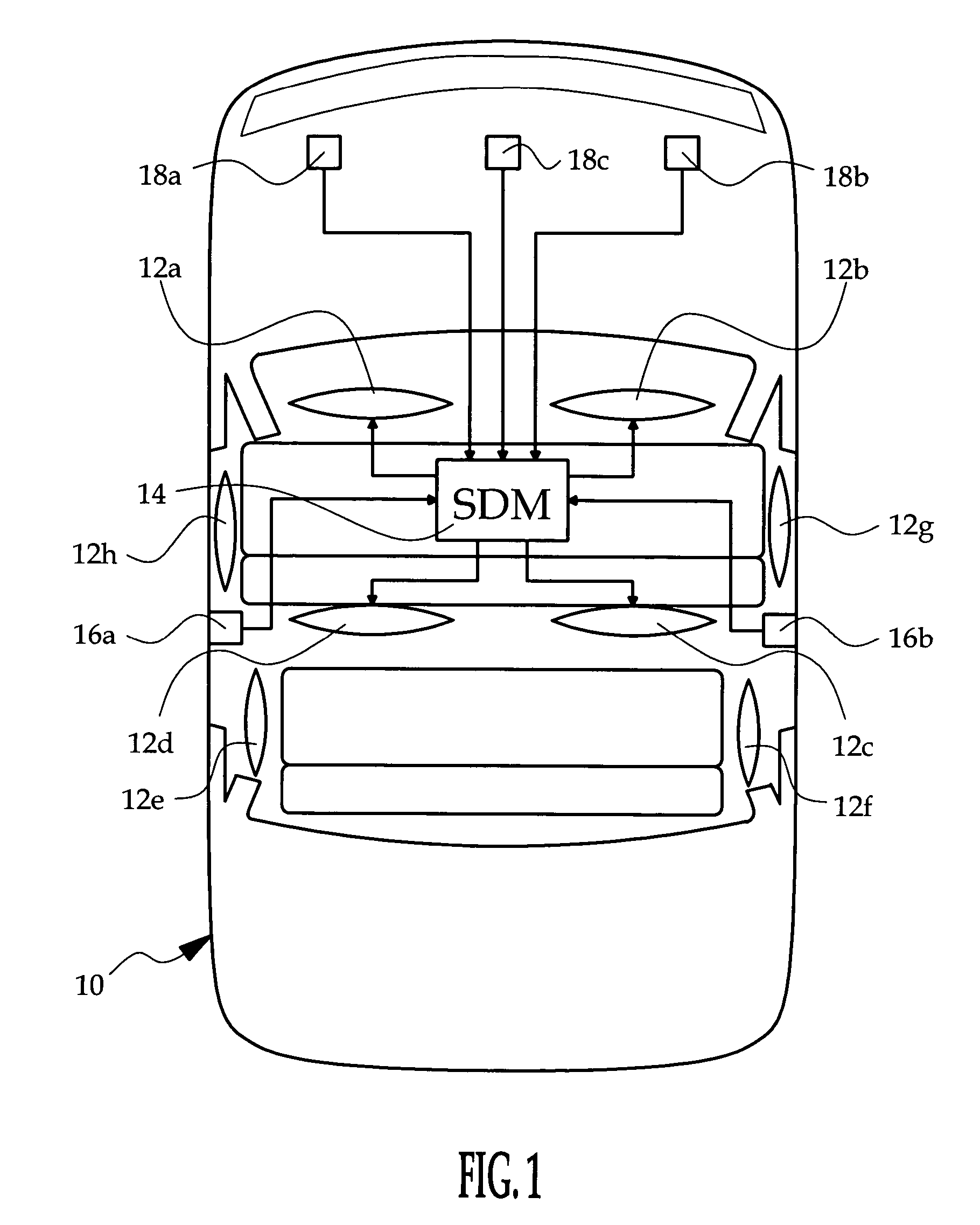
[0009]FIG. 1 generally depicts a supplemental restraint system installed in a vehicle 10. The restraint system includes a number of restraints 12a, 12b, 12c, 12d such as air bags that are variously deployed in a severe crash event to protect the vehicle occupants. The restraints may include without limitation, air bags, belt pretensioners, inflatable tubular structures, side curtains, anti-whiplash devices, etc., and it will be understood that the term airbag as used herein does not refer exclusively to a particular type of restraint. A deployment control module (SDM), designated generally by the reference numeral 14, is mounted on a frame element in a central portion of the vehicle 10. In the illustrated embodiment, the restraint system includes a longitudinal acceleration sensor within the SDM 14, a pair of side impact acceleration sensors 16a, 16b and three electronic frontal acceleration sensors 18a, 18b, 18c. The SDM 14 additionally includes a programmed microprocessor for rece...


PUM


Abstract

Occupant displacement corresponding to sensed acceleration in a crash event is determined and used to enable and disable deployment of supplemental restraints based on crash severity. The determined occupant displacement is compared to a first threshold calibrated to discriminate against disturbances due to rough roads and other non-crash events, and a second threshold calibrated to discriminate against non-deployment crash events. Deployment of supplemental restraints based on crash severity is enabled only when the determined displacement is between the first and second thresholds.

Description

TECHNICAL FIELD[0001]The present invention relates to vehicle supplemental restraint systems, and more particularly to a deployment immunity method that reliably distinguishes between deployment events and non-deployment events.BACKGROUND OF THE INVENTION[0002]Vehicle supplemental restraint systems perform a number of functions including acceleration sensing, signal processing and analysis, and deployment of one or more restraint devices such as frontal or side air bags and seat belt pretensioners in response to a sensed crash event. Typically, the acceleration signal is monitored to detect the onset of a crash event (as indicated by acceleration in excess of a reference value, for example), and then filtered or integrated over the course of the crash event to determine the change in velocity due to the crash. The change in velocity (ΔV) is indicative of the crash severity, and may be compared to a calibrated threshold to determine if the crash event is sufficiently severe to warran...

Claims


Application Information

Patent Timeline
Patent Type & Authority Patents(United States)
IPC IPC(8): E05F15/00
CPCB60R21/0132B60R21/01332B60R21/01558
Inventor SHEN, JUNQIANG
Owner APTIV TECH LTD
Why Eureka
Try Eureka