Vehicular safety systems status display

a safety system and status display technology, applied in the field of passenger safety systems, can solve the problems of difficult identification of deployable devices, driver or occupants may not be fully aware of the various safety devices that are present, and the driver may not be able to determine potential mitigating actions, so as to increase the driver's confidence in the robustness of the safety system

Inactive Publication Date: 2012-08-07
FORD GLOBAL TECH LLC
View PDF19 Cites 4 Cited by
  • Summary
  • Abstract
  • Description
  • Claims
  • Application Information

AI Technical Summary

Benefits of technology

[0007]The present invention provides both pre-crash status of the deployable devices and post-crash status of the deployable devices which may include information on resetting a device, wherein such status is preferably displayed using a graphic and textual display panel present in the vehicle in connection with another system, such as a vehicle navigation system. Advantages include 1) informing the driver of the safety features present in the vehicle and of their actual readiness to respond in the event of a crash, 2) informing the driver which actions were taken in response to a crash event, thereby increasing the driver's confidence in the robustness of the safety systems overall, 3) providing a repository for valuable information for accident reconstruction, and 4) the ability to interface with other vehicular systems for providing automatic notification and details of crash events to remotely located emergency services.

Problems solved by technology

In view of the potential variety of devices, the vehicle driver or occupants may not be fully aware of the various safety devices that are present in the vehicle.
However, identification of the faulted system is not usually specified in the driver notification, so that the driver may not be able to determine potential mitigating actions when using the vehicle prior to taking the vehicle to a repair facility (e.g., the driver would not know to relocate a passenger from a front passenger seat to a rear driver-side seat when a passenger side curtain airbag is faulted unless notified of the specific fault).
Due to the nature of some deployable devices, when a crash event occurs and deployable devices have deployed, it may be difficult for the driver or occupants to identify all of the deployable devices that have in fact been deployed.
Consequently, they may be unable to restart the vehicle when desired.
However, there is no disclosure of any automatic system for generating guidance information to assist the driver in the reset procedure itself.

Method used


Image

  • Vehicular safety systems status display
  • Vehicular safety systems status display
  • Vehicular safety systems status display

Examples


Embodiment Construction

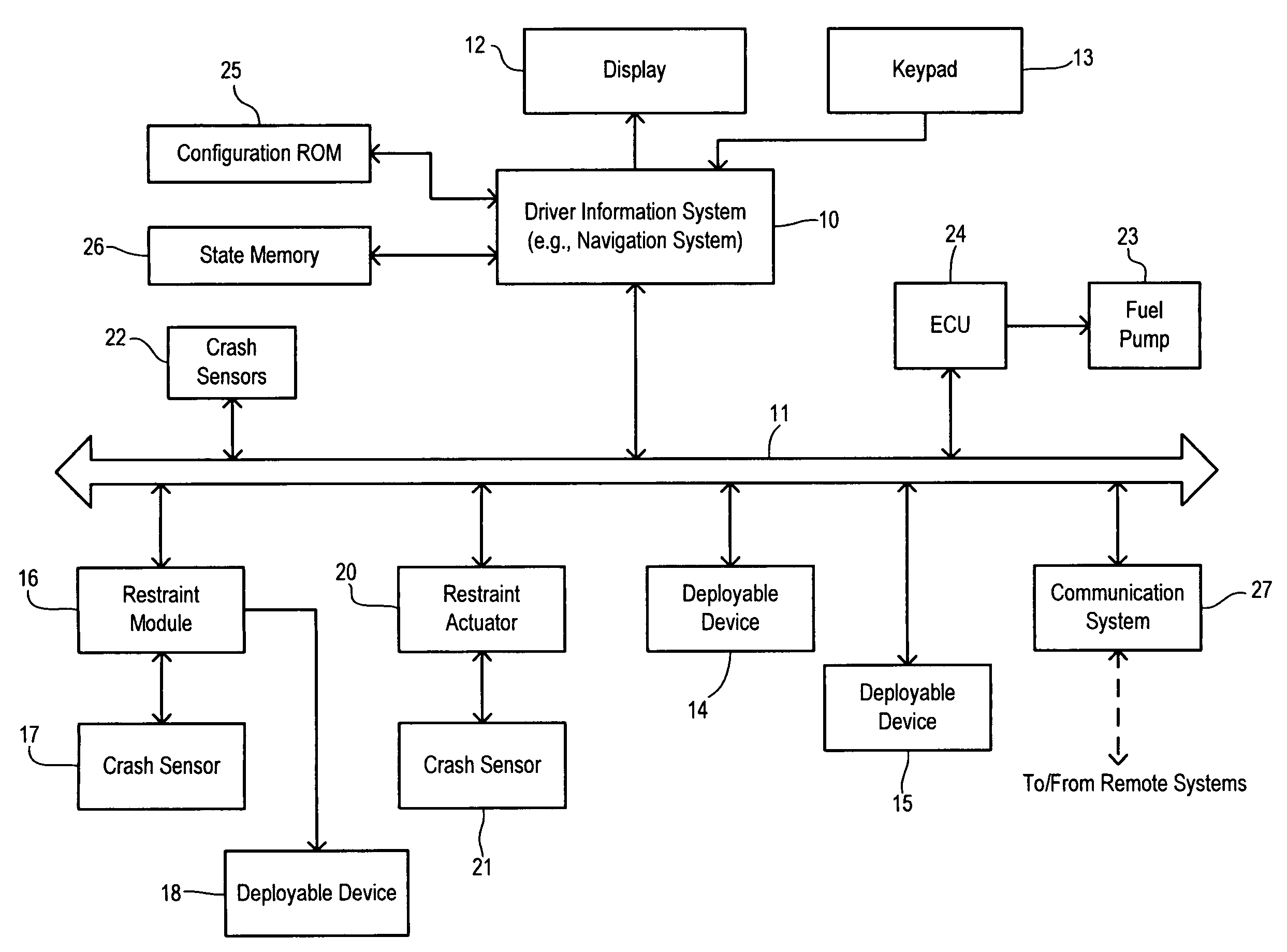
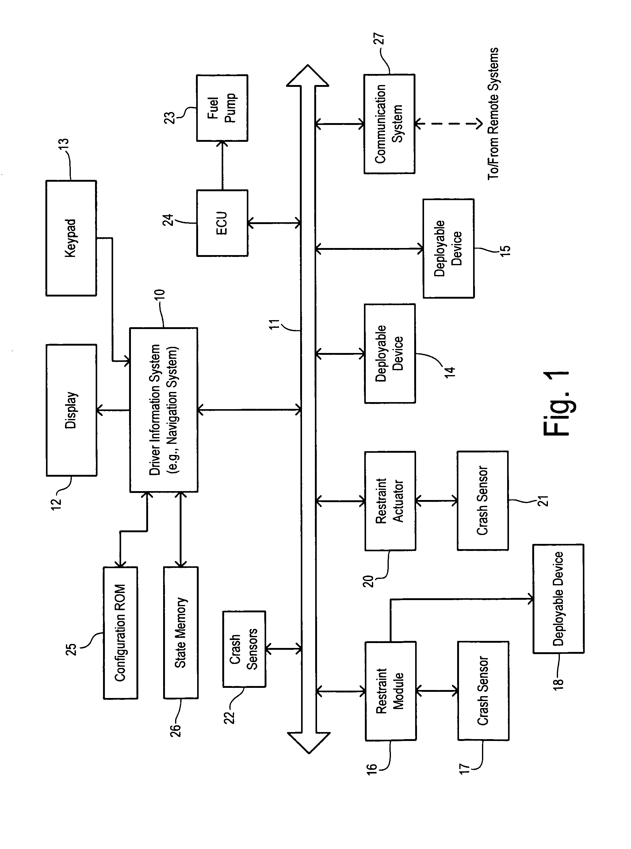
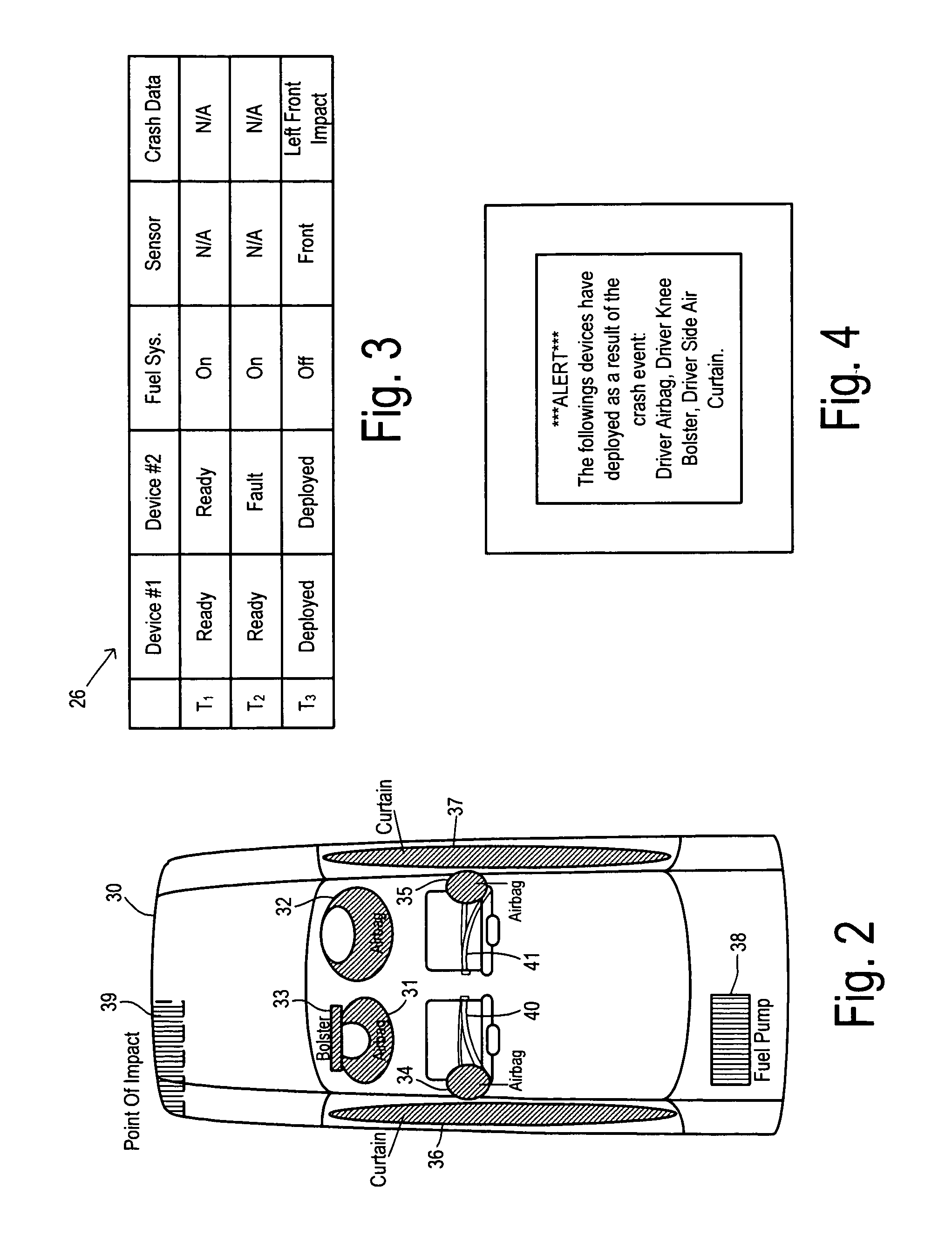
[0013]The present invention employs an in-vehicle graphics display, such as a navigation screen for a vehicle navigation system (e.g., the Sync System available from Ford Motor Company), to convey information about deployable safety devices both prior to and following any crash events. A pictorial, overhead view of the vehicle with readiness icons representing the various deployable features can be used to inform the driver about the safety devices within their vehicle. After a crash event, the display may then indicate which devices have been deployed and any reset actions that can be taken to restore a deployed device to full readiness.

[0014]A first preferred embodiment of a vehicle safety system is shown in FIG. 1. An electronic control module for a driver information system 10 (such as a navigation system) is coupled to a vehicle multiplex communication bus 11 (such as a CAN bus). A display screen 12 coupled to driver information system control module 10 may comprise an LCD disp...


PUM


Abstract

Apparatus for a road vehicle has a plurality of deployable devices, each performing a crash safety function. A device controller controls deployment of a respective deployable device and that provides respective status messages according to a deployment status of the respective deployable device. Respective status messages for each deployable device include a ready message and a deployed message. A crash sensor detects a crash event when the vehicle is involved in an impact, wherein the crash sensor generates a crash event message. A display controller is coupled to the deployable devices to receive the status messages and coupled to the crash sensor to receive the crash event message. A display is coupled to the display controller for displaying status information to a driver of the vehicle. The displayed status information includes pre-crash status of the deployable devices and post-crash status of the deployable devices.

Description

CROSS REFERENCE TO RELATED APPLICATIONS[0001]Not Applicable.STATEMENT REGARDING FEDERALLY SPONSORED RESEARCH[0002]Not Applicable.BACKGROUND OF THE INVENTION[0003]The present invention relates in general to passenger safety systems in road vehicles, and, more specifically, to a system for informing a driver of pre-crash and post-crash status of deployable devices in the safety system.[0004]Since the first introduction of airbag supplemental restraint systems, the safety capability of motor vehicles has increased dramatically. Restraint systems have become highly adaptive, and the possible combinations of devices that may be deployed during a crash event are many. Examples of deployable devices that may be installed on a particular vehicle include driver and passenger front airbags, knee bolsters, side airbags, side curtain airbags, pre-tensioning belt systems, and fuel delivery systems. In view of the potential variety of devices, the vehicle driver or occupants may not be fully awar...

Claims


Application Information

Patent Timeline
Patent Type & Authority Patents(United States)
IPC IPC(8): G06F19/00G06F17/00
CPCB60R21/0134B60R21/0136
Inventor TIPPY, DAVID J.
Owner FORD GLOBAL TECH LLC
Why Eureka
Try Eureka