System for Controlling a Droplet Actuator

a technology of actuator and droplet, which is applied in the direction of diaphragm, process and machine control, program control, etc., can solve the problems of large supporting system, limited continuous flow system, and difficulty in achieving high degree of functional integration and control in conventional continuous flow system

Inactive Publication Date: 2008-01-10
ADVANCED LIQUID LOGIC +1
View PDF60 Cites 140 Cited by
  • Summary
  • Abstract
  • Description
  • Claims
  • Application Information

AI Technical Summary

Problems solved by technology

Continuous flow systems are limited by the fact that liquid transport is physically confined to permanently etched channels.
These approaches involve complex channeling and require large supporting systems in the form of external pumps, valves and power supplies.
These restrictions make it difficult to achieve high degrees of functional integration and control in conventional continuous-flow systems, particularly in realizing a handheld device at the point of sample collection.
Moreover, the fluid flow is unidirectional and therefore is not easily reconfigurable or programmable.
In addition, the technological limitations of continuous-flow channel systems do not allow the integration of multiple formats of analysis such as PCR, immunoassays, chemistry, and cell handling together onto a single chip.
Even where these technologies miniaturize the assay on a lab-on-a-chip they require a large instrument to manage even limited operations on the chip.
Moreover, in many instances it may be virtually impossible to preserve samples for transport to a central lab.
Even when such preservation is possible, the extensive procedures required may render preservation and transport to a central lab economically unfeasible.
Alternatively, researchers may be forced to accept some diminishment in accuracy of analysis caused by transport under less than ideal conditions.

Method used


Image

  • System for Controlling a Droplet Actuator
  • System for Controlling a Droplet Actuator
  • System for Controlling a Droplet Actuator

Examples


Embodiment Construction

[0051] The present invention relates to systems and methods for controlling droplet movements on a droplet microactuator, including software and systems for creating code for controlling droplet movements. The present invention also relates to a droplet microactuator device, system and method for processing and / or analyzing samples, including the provision of a portable or handheld device.

[0052] 8.1 Systems and Methods for Droplet Microactuator Operations

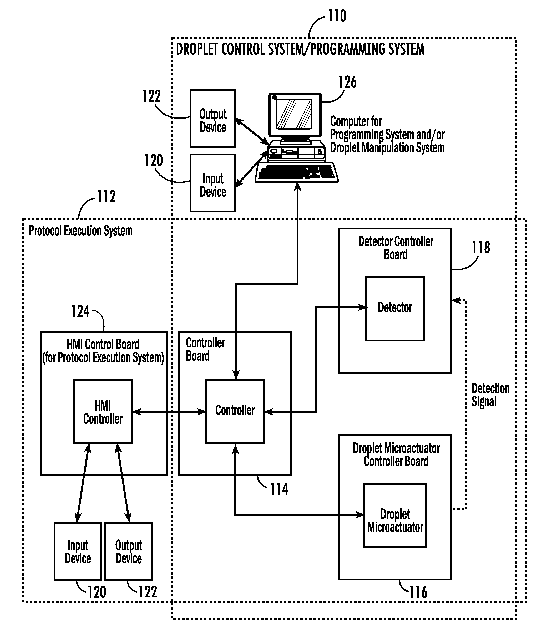
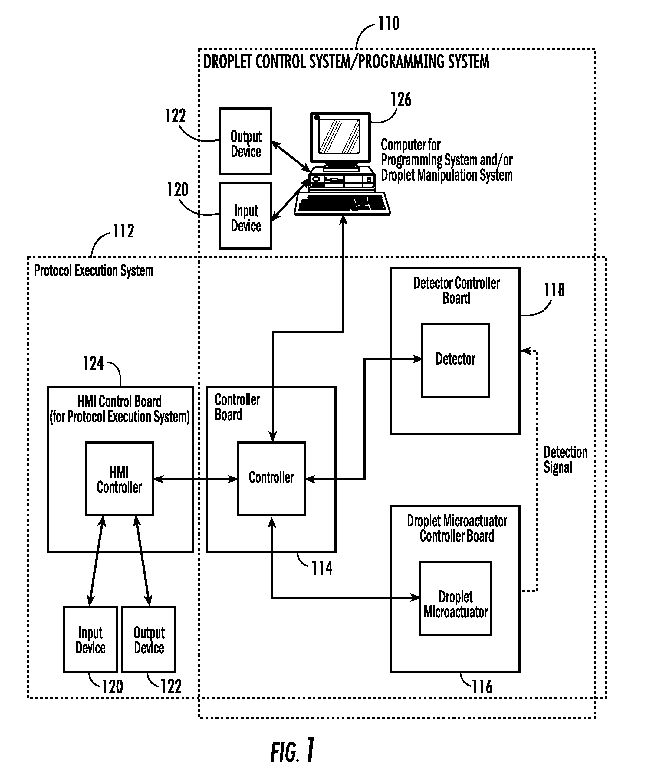
[0053] One aspect of the present invention provides a droplet control system, a programming system, a protocol execution system, as well as integrated systems including the droplet control system, the programming system, and / or the protocol execution system. A method or computer useable instructions for controlling these systems is also provided. The droplet control system permits a user to control droplet microactuator system functions, such as droplet operations and detector operations. The programming system permits a user to d...


PUM

PropertyMeasurementUnit
volumeaaaaaaaaaa
thicknessaaaaaaaaaa
dielectric constantaaaaaaaaaa

Abstract

Systems for controlling a droplet microactuator are provided. According to one embodiment, a system is provided and includes a controller, a droplet microactuator electronically coupled to the controller, and a display device displaying a user interface electronically coupled to the controller, wherein the system is programmed and configured to permit a user to effect a droplet manipulation by interacting with the user interface. According to another embodiment, a system is provided and includes a processor, a display device electronically coupled to the processor, and software loaded and/or stored in a storage device electronically coupled to the controller, a memory device electronically coupled to the controller, and/or the controller and programmed to display an interactive map of a droplet microactuator. According to yet another embodiment, a system is provided and includes a controller, a droplet microactuator electronically coupled to the controller, a display device displaying a user interface electronically coupled to the controller, and software for executing a protocol loaded and/or stored in a storage device electronically coupled to the controller, a memory device electronically coupled to the controller, and/or the controller.

Description

2 RELATED APPLICATIONS [0001] This application is a continuation of International Patent Application No. PCT / US2007 / 011298, entitled “Droplet Manipulation Systems,” filed May 9, 2007, pending, which claims the benefit of, is related to, and incorporates by reference related provisional U.S. Patent Application No. 60 / 746,797, entitled “Portable Analyzer Using Droplet-Based Microfluidics,” filed on May 9, 2006 and 60 / 806,412, entitled “Systems and Methods for Droplet Microactuator Operations,” filed on Jun. 30, 2006.1 GRANT INFORMATION [0002] The work leading to this invention was supported at least in part by NIH Grant Nos. 1 R44 DK066956-01; 1 R43 GM072155-01; 1 R21 HG003706-01; NNJ06JD53C; and 5 U01 AI066590-02. The United States Government may have certain rights in the invention described herein.3 FIELD OF THE INVENTION [0003] Embodiments of the present invention relate to systems for controlling a droplet microactuator, including software and systems for creating code for contro...

Claims


Application Information

Patent Timeline
Patent Type & Authority Applications(United States)
IPC IPC(8): G01N27/00
CPCB01L3/502792B01L2200/143B01L2400/0427B01L2300/0816B01L2300/027
Inventor PAIK, PHILIP Y.POLLACK, MICHAEL G.STURMER, RYAN A.SMITH, GREGORY F.BRAFFORD, KEITH R.PAMULA, VAMSEE K.
Owner ADVANCED LIQUID LOGIC
Why Eureka
Try Eureka