Droplet actuator analyzer with cartridge

a technology of actuator and droplet, which is applied in the direction of container/bottle construction, small article dispensing, rigid containers, etc., can solve the problems of large supporting systems, limited continuous flow systems, and difficult to achieve high degree of functional integration and control in conventional continuous flow systems

Inactive Publication Date: 2011-05-10
ADVANCED LIQUID LOGIC +1
View PDF109 Cites 141 Cited by
  • Summary
  • Abstract
  • Description
  • Claims
  • Application Information

AI Technical Summary

Benefits of technology

[0159]In another embodiment of the detection subsystem of the invention the chemical assay is designed to produce a fluorescent signal. The reaction takes place in the presence of an optical window and / or the products or some portion of the reaction products are transported to the optical window. The advantage of the invention relative to fluorescent detection relates to the discrete nature of the droplet-based system, wherein very accurate volumes of sample and reagent can be mixed, and the level of fluorescent output is more carefully controlled.
[0160]In addition, many samples can be presented to a single detector, as droplets can be cycled in view of the detector on a schedule designed to measure fluorescent output as a function of time. Thus a single detector can be used to simultaneously follow multiple reactions over time. In other systems with less complex liquid handling systems separate detectors must be used if simultaneous results are required. In one embodiment, illustrated in FIG. 5B, the invention makes use of a photomultiplier tube mounted on the analyzer portion of the system for detecting and measuring weak light signals emitted from the droplet microactuator.
[0161]Similarly, in another embodiment, the chemical assay is designed to produce a luminescent output. A luminescence detector is placed opposite the same or another optical window. The reaction takes place opposite the optical window and / or the products or some portion of the reaction products are transported to the optical window. The luminescence detection approach is typically a more sensitive detection technique. Otherwise, the technique benefits from advantages analogous to those described above for fluorescence detection.
[0162]In another embodiment the concentration of a target analyte is known to absorb light of a particular wavelength as a function of concentration. The droplet, once prepared for analysis, is placed in the path of light, and a photodetector is used to measure the change in light output.
[0163]These detection methods can be used in combination to conduct multiple assays simultaneously using the same or different detectors. A single assay can also be measured using multiple detection techniques to enhance confidence in the output.8.2.4 Assays
[0164]The system of the invention may be programmed to execute various assay protocols. Multi-step enzymatic assays, for example, involve the sequential addition of materials to the sample. The end result is typically a color change, luminescent or output, for example, which can be detected by optical means.

Problems solved by technology

Continuous flow systems are limited by the fact that liquid transport is physically confined to permanently etched channels.
These approaches involve complex channeling and require large supporting systems in the form of external pumps, valves and power supplies.
These restrictions make it difficult to achieve high degrees of functional integration and control in conventional continuous-flow systems, particularly in realizing a handheld device at the point of sample collection.
Moreover, the fluid flow is unidirectional and therefore is not easily reconfigurable or programmable.
In addition, the technological limitations of continuous-flow channel systems do not allow the integration of multiple formats of analysis such as PCR, immunoassays, chemistry, and cell handling together onto a single chip.
Even where these technologies miniaturize the assay on a lab-on-a-chip they require a large instrument to manage even limited operations on the chip.
Moreover, in many instances it may be virtually impossible to preserve samples for transport to a central lab.
Even when such preservation is possible, the extensive procedures required may render preservation and transport to a central lab economically unfeasible.
Alternatively, researchers may be forced to accept some diminishment in accuracy of analysis caused by transport under less than ideal conditions.

Method used


Image

  • Droplet actuator analyzer with cartridge
  • Droplet actuator analyzer with cartridge
  • Droplet actuator analyzer with cartridge

Examples


Embodiment Construction

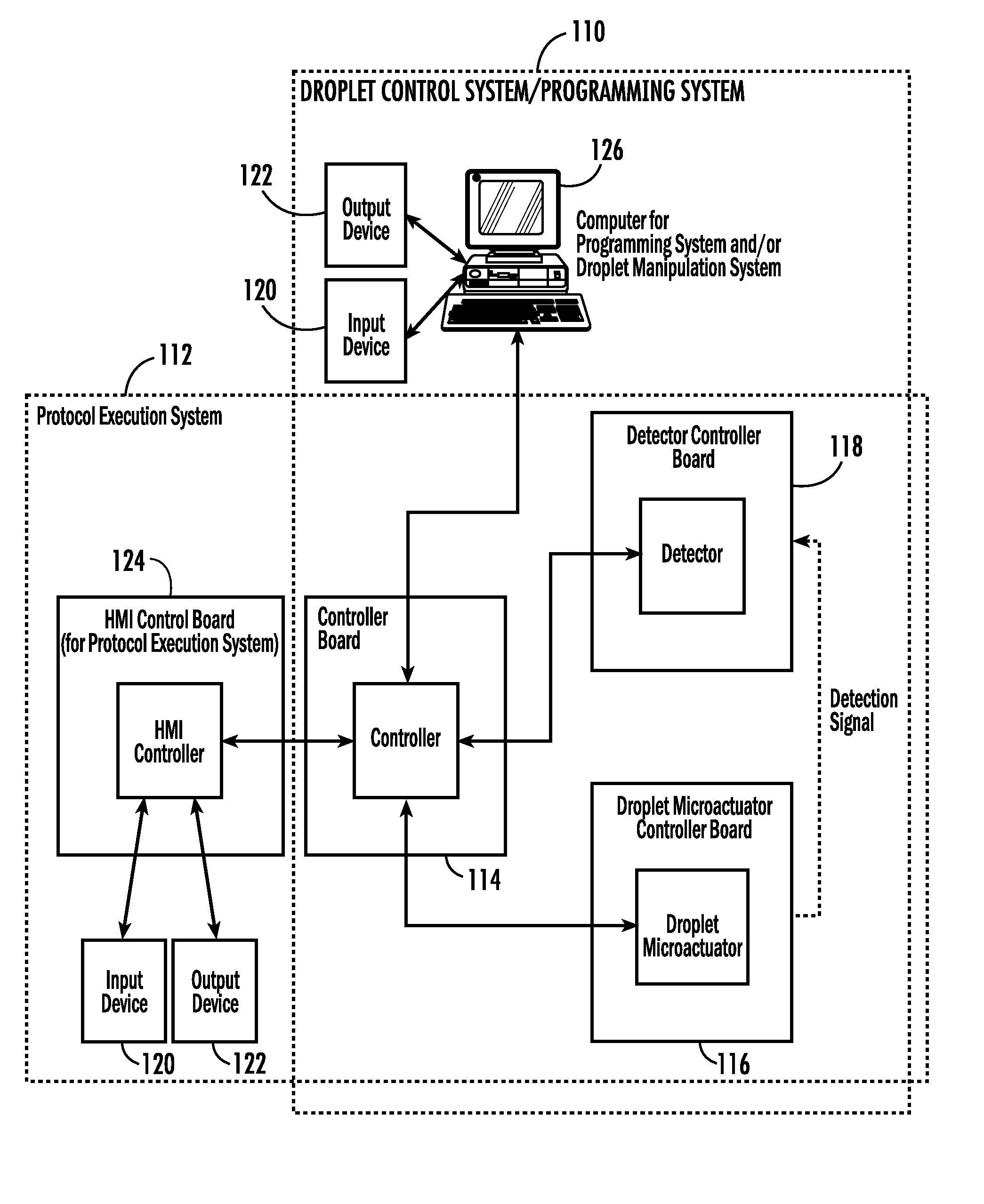
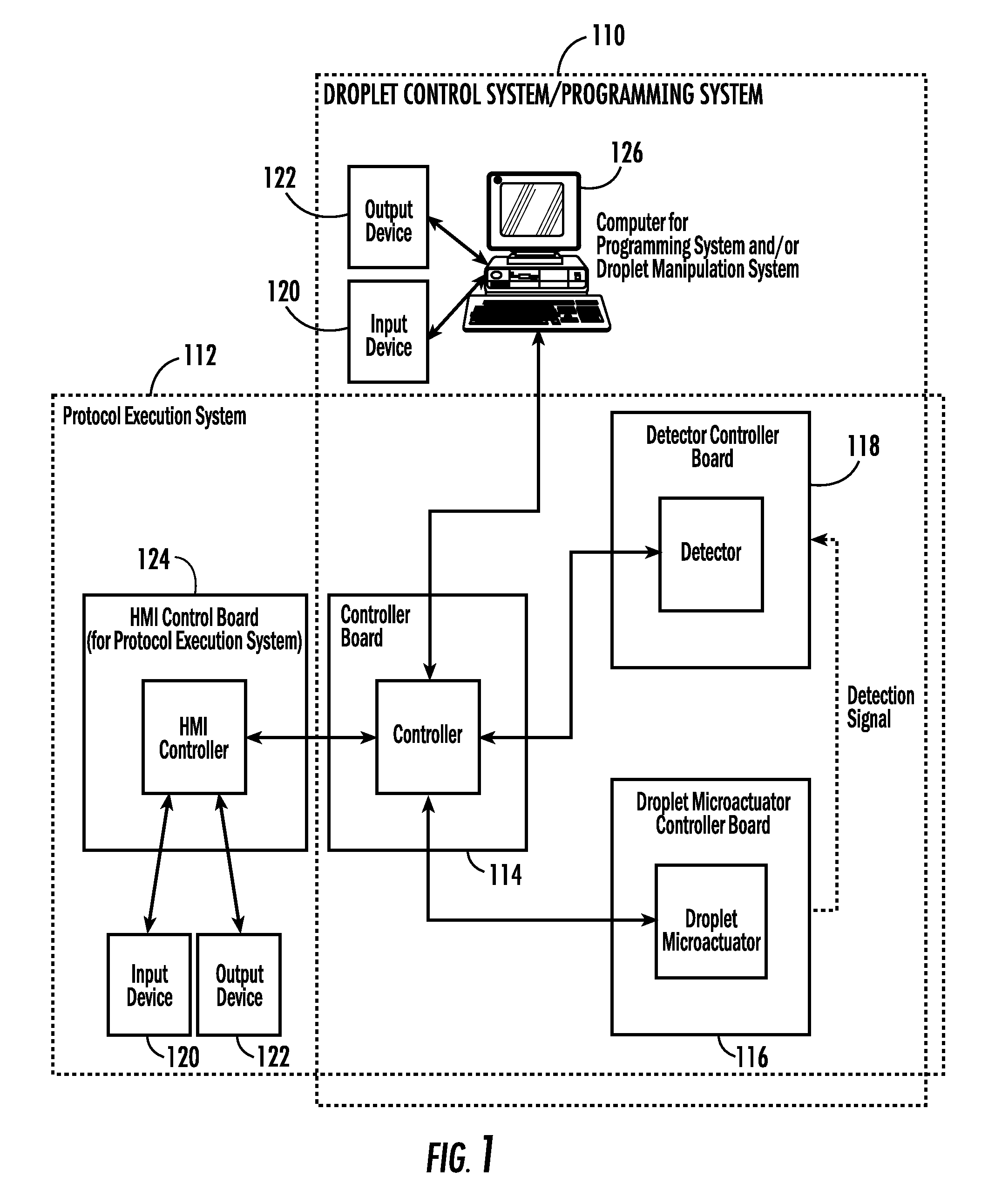
[0047]The present invention relates to systems and methods for controlling droplet movements on a droplet microactuator, including software and systems for creating code for controlling droplet movements. The present invention also relates to a droplet microactuator device, system and method for processing and / or analyzing samples, including the provision of a portable or handheld device.

8.1 Systems and Methods for Droplet Microactuator Operations

[0048]One aspect of the present invention provides a droplet control system, a programming system, a protocol execution system, as well as integrated systems including the droplet control system, the programming system, and / or the protocol execution system. A method or computer useable instructions for controlling these systems is also provided. The droplet control system permits a user to control droplet microactuator system functions, such as droplet operations and detector operations. The programming system permits a user to develop soft...


PUM

PropertyMeasurementUnit
volumeaaaaaaaaaa
thicknessaaaaaaaaaa
dielectric constantaaaaaaaaaa

Abstract

A droplet actuator with cartridge is provided. According to one embodiment, a sample analyzer is provided and includes an analyzer unit comprising electronic or optical receiving means, a cartridge comprising self-contained droplet handling capabilities, and a wherein the cartridge is coupled to the analyzer unit by a means which aligns electronic and / or optical outputs from the cartridge with electronic or optical receiving means on the analyzer unit. According to another embodiment, a sample analyzer is provided and includes a sample analyzer comprising a cartridge coupled thereto and a means of electrical interface and / or optical interface between the cartridge and the analyzer, whereby electrical signals and / or optical signals may be transmitted from the cartridge to the analyzer.

Description

1 RELATED APPLICATIONS[0001]This application is a continuation of International Patent Application No. PCT / US2007 / 011298, entitled “Droplet Manipulation Systems,” filed May 9, 2007, pending, which claims the benefit of, is related to, and incorporates by reference related provisional U.S. Patent Application Nos. 60 / 746,797, entitled “Portable Analyzer Using Droplet-Based Microfluidics,” filed on May 9, 2006 and 60 / 806,412, entitled “Systems and Methods for Droplet Microactuator Operations,” filed on Jun. 30, 2006.2 GRANT INFORMATION[0002]This invention was made with government support under DK066956, GM072155, HG003706, AI066590 awarded by National Institutes of Health; and under NNJ06JD53C awarded by NASA. The government has certain rights in the invention.3 FIELD OF THE INVENTION[0003]Embodiments of the present invention relate to a droplet actuator with cartridge, which may be provided as a portable or hand-held device. Embodiments may be conveniently used to provide analysis at ...

Claims


Application Information

Patent Timeline
Patent Type & Authority Patents(United States)
IPC IPC(8): G01N33/00G01N27/00G01N15/06B65D35/28B65D35/00G01N21/00G05B21/00
CPCB01F13/0071B01L3/502715B01L3/502792B01F13/0076G01N33/49B01L7/52B01L7/525B01L2200/027B01L2200/0668B01L2200/148B01L2200/16B01L2300/024B01L2300/0654B01L2300/0816B01L2300/0819B01L2300/0861B01L2300/0864B01L2300/0867B01L2300/089B01L2300/1827B01L2400/0406B01L2400/0415B01L2400/043B01L2400/0436B01L2400/0442B01L2400/0448B01L2400/0683B01F33/3021B01F33/3031
Inventor SMITH, GREGORY F.STURMER, RYAN A.PAIK, PHILIP Y.SRINIVASAN, VIJAYPOLLACK, MICHAEL G.PAMULA, VAMSEE K.BRAFFORD, KEITH R.WEST, RICHARD M.
Owner ADVANCED LIQUID LOGIC
Why Eureka
Try Eureka