Automated flare control

a technology of automatic flare control and control method, which is applied in the direction of lighting and heating apparatus, incinerator apparatus, combustion types, etc., can solve the problems of unfavorable emissions, emissions present environmental pollution issues, and the combustion efficiency of flares cannot provide a direct correlation to whether or not, so as to increase the steam injection rate and limit the smoke level

Active Publication Date: 2011-08-11
PHILLIPS 66 CO
View PDF34 Cites 28 Cited by
  • Summary
  • Abstract
  • Description
  • Claims
  • Application Information

AI Technical Summary

Benefits of technology

[0009]According to one embodiment, a method of monitoring and controlling a flare includes detecting particulate matter emitted from a flare and detecting a parameter of the flare indicative of combustion efficiency of the flare. The detecting of the particulate matter is independent from combustion efficiency of the flare. The method further includes adjusting rate of smoke suppressant injection to the flare based on signals output from the detecting of the particulate mater and the parameter that is indicative of the combustion efficiency in order to limit smoke and emission level of unburned volatile organic compounds from the flare.
[0010]For one embodiment, a method of monitoring and controlling a flare includes detecting an attribute influenced by particulate matter emitted from the flare such that a first signal is produced. Measuring at least one of temperature of the flare and volatile organic compounds emitted beyond a flame of the flare produces a second signal. In addition, the method includes increasing rate of steam injection to the flare in order to limit smoke level upon the first signal reaching a first threshold and decreasing the rate of steam injection to the flare in order limit combustion inefficiency upon the second signal reaching a second threshold.

Problems solved by technology

The flare can produce undesirable emissions in form of particulate smoke and smokeless release of the waste gas that remains unburned from inefficient combustion.
Both types of the emissions present environmental pollution issues.
The combustion efficiency of the flare fails to provide a direct correlation to whether or not the flare produces smoke.
Even with almost complete combustion, the flare may produce unacceptable levels of the smoke.
The flare may however not generate any smoke while operating at unacceptable low levels for the combustion efficiency.
Given lack of correlation between the combustion efficiency and smoking, problems can arise with these techniques resulting in the flare still emitting either the smoke or smokeless release of the waste gas that remains unburned.
In addition, introducing more of the steam to the flare may further reduce the combustion efficiency when assuming that the combustion efficiency being below a certain point implies tendency for the flare to produce the smoke.

Method used


Image

  • Automated flare control
  • Automated flare control
  • Automated flare control

Examples


Embodiment Construction

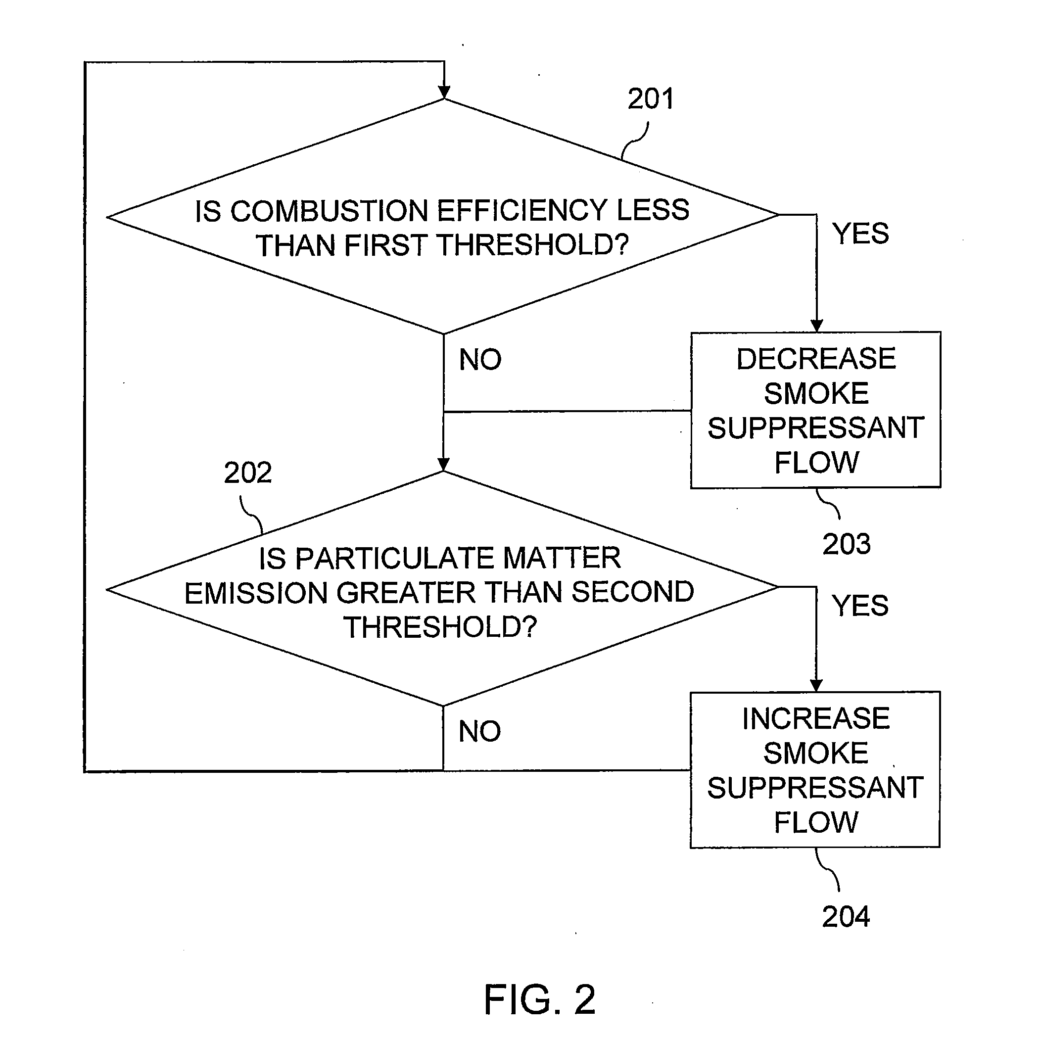
[0014]Embodiments of the invention relate to control of smoke suppressant flow rate to a flare that disposes of combustible gas, such as waste from refineries and chemical plants. One or more detectors produce signals that enable separate monitoring of both particulate emissions from the flare and combustion efficiency of the flare. Adjusting the flow rate of the smoke suppressant to the flare in response to such dual monitoring facilitates operation of the flare so as to manage environmental pollution caused by unburned volatile organic compounds and smoke emitted from the flare.

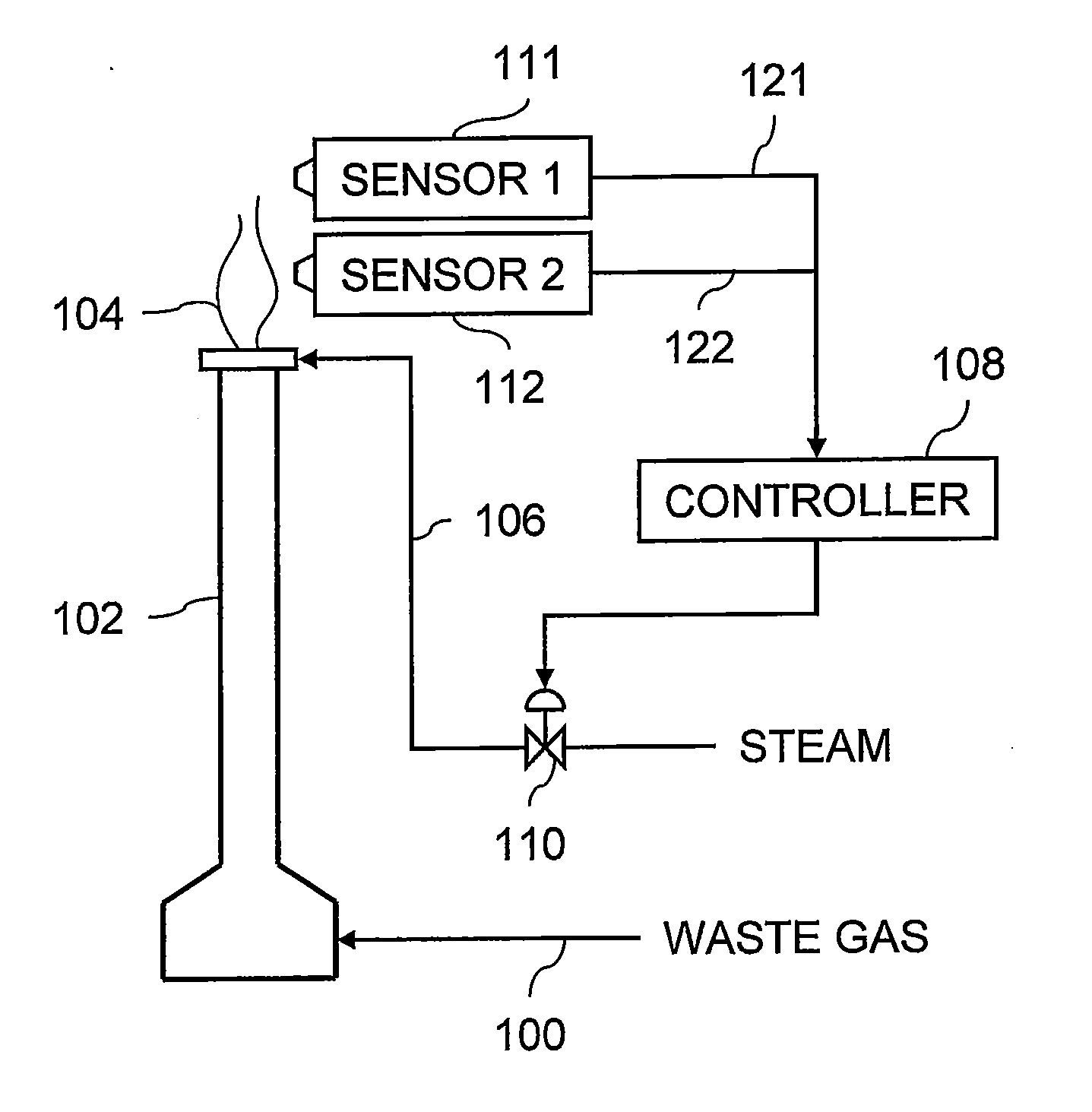
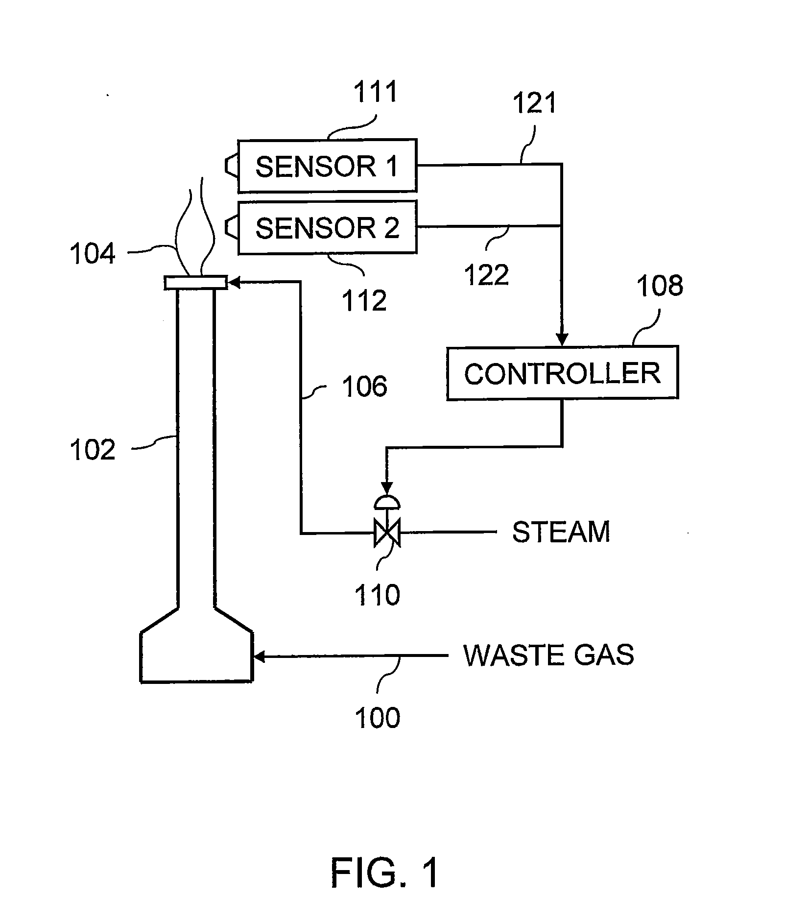
[0015]FIG. 1 illustrates a system that includes a stream of waste gas 100 supplied to a flare 102. The waste gas 100 may contain combustible hydrocarbons that come from a refinery or plant and are burned at a flame 104 exiting the flare 102. A smoke suppressant line 106 supplies steam and / or air to the flare 102 for injection into the flame 104.

[0016]The system further includes a controller 108 that operate...


PUM


Abstract

Methods and apparatus relate to control of smoke suppressant flow rate to a flare that disposes of combustible gas, such as waste from refineries and chemical plants. One or more detectors produce signals that enable separate monitoring of both particulate emissions from the flare and combustion efficiency of the flare. Adjusting the flow rate of the smoke suppressant to the flare in response to such dual monitoring facilitates operation of the flare so as to manage environmental pollution caused by unburned volatile organic compounds and smoke emitted from the flare.

Description

CROSS-REFERENCE TO RELATED APPLICATIONS[0001]This application is a non-provisional application which claims the benefit of and priority to U.S. Provisional Application Ser. No. 61 / 302,853 filed Feb. 9, 2010, entitled “Automated Flare Control,” which is hereby incorporated by reference in its entirety.STATEMENT REGARDING FEDERALLY SPONSORED RESEARCH OR DEVELOPMENT[0002]NoneFIELD OF THE INVENTION[0003]Embodiments of the invention relate to methods and systems for monitoring and controlling a flare.BACKGROUND OF THE INVENTION[0004]Refineries and chemical plants often discharge combustible waste gas to a flare. The flare can produce undesirable emissions in form of particulate smoke and smokeless release of the waste gas that remains unburned from inefficient combustion. Both types of the emissions present environmental pollution issues.[0005]The combustion efficiency of the flare fails to provide a direct correlation to whether or not the flare produces smoke. Even with almost complete...

Claims


Application Information

Patent Timeline
Patent Type & Authority Applications(United States)
IPC IPC(8): F23N5/26
CPCF23G7/085F23G5/50
Inventor TULLOS, ERIN E.
Owner PHILLIPS 66 CO
Why Eureka
Try Eureka