Single-use pneumatic safety syringe providing gas-driven needle retraction

a pneumatic safety and single-use technology, applied in the field of pneumatic safety syringes, can solve the problems of affecting the potential exposure to communicable diseases, and the spread of communicable and dangerous diseases, so as to prevent the re-extension of the safety mechanism from extending out of the barrel, the effect of reliably controlling and relatively simple operation

Active Publication Date: 2006-05-25
L O M LAB
View PDF65 Cites 134 Cited by
  • Summary
  • Abstract
  • Description
  • Claims
  • Application Information

AI Technical Summary

Problems solved by technology

It is well known that many dangerous communicable diseases are spread through contacting the body fluids of an infected person.
However, it sometimes happens that persons attempting to cap a used needle miss the cap and accidentally stab themselves, resulting in potential exposure to communicable diseases.
Further, spread of communicable and dangerous diseases is effected by drug-addicted individuals sharing and re-using needles and syringes intended for single use.
However, the protective sheath may interfere with use of the syringe as it may obstruct the view of the point the needle is to be inserted into the patient.
In addition, it is inconvenient to use; after injection, the user must change the user's hand position on the syringe in order to breach the double wall and activate the sheath.
However, this device suffers from the disadvantages that the casing may interfere with the use of the syringe in making injections as it is designed to fit over a conventional syringe thereby changing the size and feel of the device as compared to a conventional syringe.
In addition, a considerable amount of material is necessary in order to make the protective sheath, increasing the expense of both making and disposing of the device.
This device suffers from the disadvantage that accidental re-extension of the needle is possible if the plunger arm is not snapped off by the user.
A further disadvantage of this device is that if the user does not apply a constant injection force, there is the possibility that the plunger will retract under the vacuum before the medicament is completely injected, thereby causing the syringe to work in reverse.
However, this device still has the disadvantage that if the user does not apply a constant injection force, there is the possibility that the plunger will retract under the vacuum before the medicament is completely injected, thereby causing the syringe to work in reverse.
Further, due to the retention of the plunger in the locked extended position after retraction, the extended syringe takes more space in disposal containers than do conventional syringes.

Method used


Image

  • Single-use pneumatic safety syringe providing gas-driven needle retraction
  • Single-use pneumatic safety syringe providing gas-driven needle retraction
  • Single-use pneumatic safety syringe providing gas-driven needle retraction

Examples


Embodiment Construction

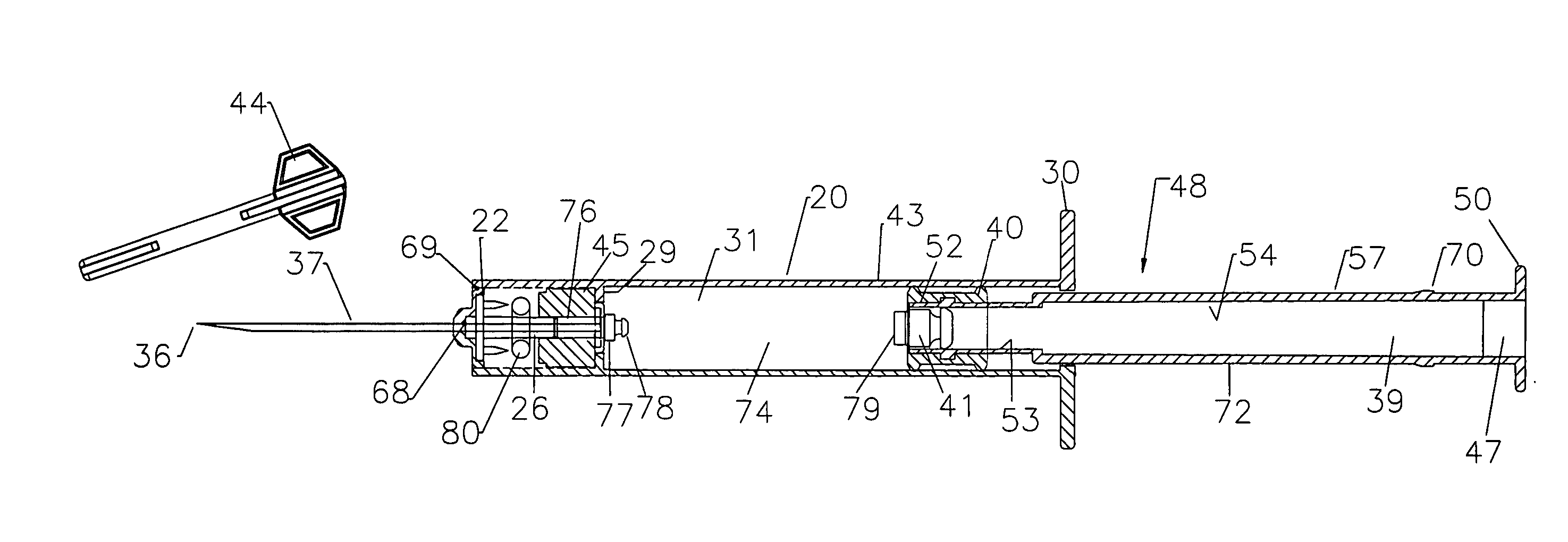
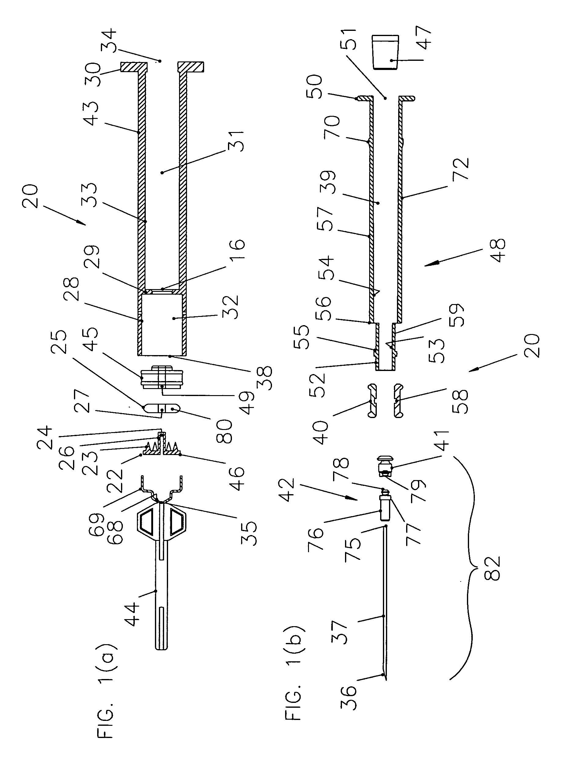
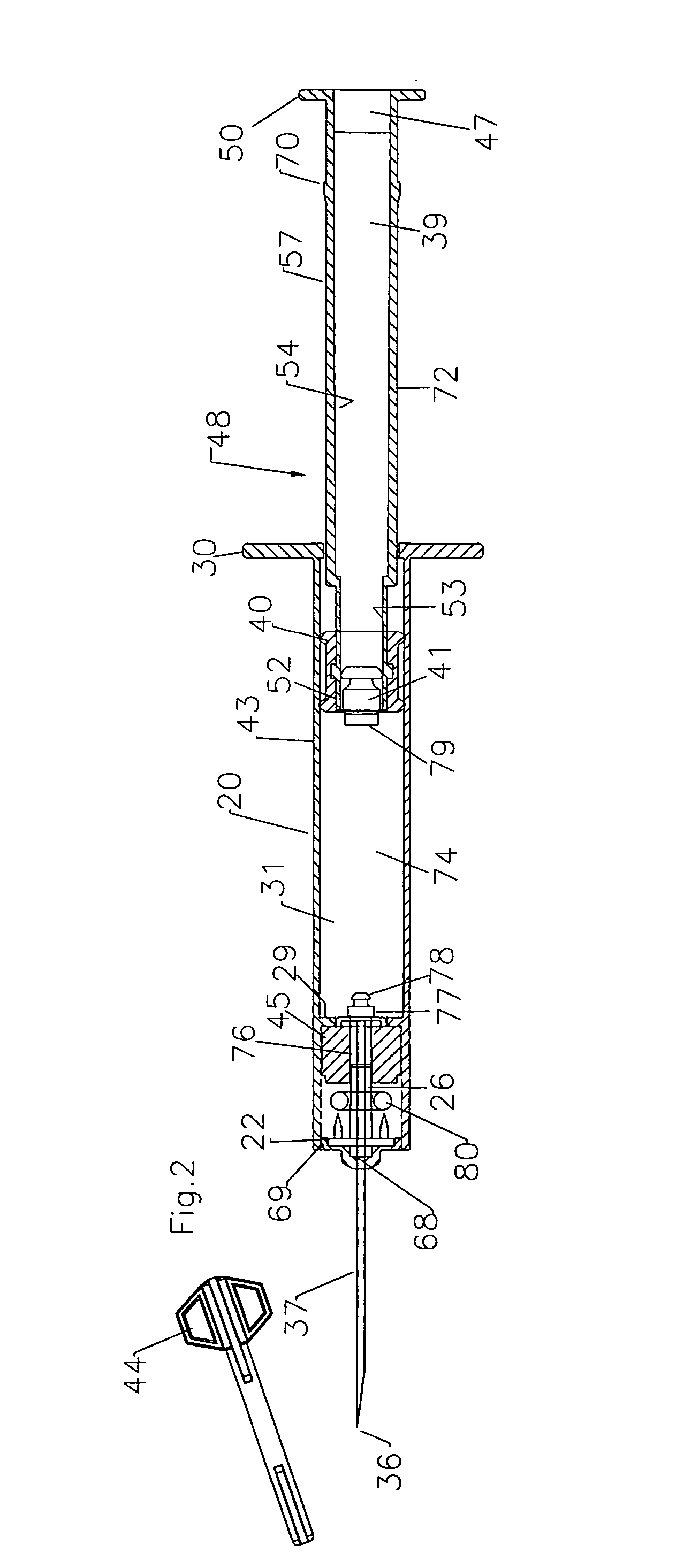
[0081] In the drawings and in this description, exemplary embodiments of syringes and syringe components made in accordance with various facets of the invention are illustrated. It is to be understood in this description that “the invention” may include a number of different inventive concepts and implementations, and that the words “the invention” may refer to one or more of them, as the context may require. The description and drawings illustrate representative embodiments of the invention and act as an aid to comprehension, and are not intended as a definition of the limits of the invention. The limits of the invention are as defined by the claims.

[0082] While in this specification, information is stated about materials selections and other parameters applicable to syringe designs according to the invention, (the syringes described herein had not gone into commercial production as of this writing), the reader should keep in mind that an empirical approach should be taken to the ...


PUM


Abstract

A pneumatic retractable syringe has a plunger having an interior retraction lumen. The plunger and syringe barrel have cooperating locking elements so that the plunger is locked after use within the syringe barrel. After injection of medicament is completed, the needle is retracted into the lumen by compressed gas that is released from a gas cell within the syringe when the gas cell is ruptured just before the plunger reaches the end of its downstream path of travel.

Description

FIELD OF THE INVENTION [0001] The invention relates generally to a pneumatic safety syringe of the type for use with a hypodermic needle. In a syringe according to the present invention, following use of the syringe, the plunger is locked into the syringe body (barrel) and the needle is retracted into the retraction lumen of the plunger, thereby preventing accidental stabbing after use and unwanted re-extension of the plunger out of the barrel. The retraction of the needle is effected by the release of gas under pressure or other suitable pneumatic means; e.g. obtained by puncturing a gas cell or by causing a chemical reaction that will release gas. A syringe of this general type is sometimes referred to as a “retractable syringe”; what is meant by this term is that the needle retracts within the body of the syringe. BACKGROUND OF THE INVENTION [0002] It is well known that many dangerous communicable diseases are spread through contacting the body fluids of an infected person. After...

Claims


Application Information

Patent Timeline
Patent Type & Authority Applications(United States)
IPC IPC(8): A61M5/00A61M5/32
CPCA61M5/3234A61M2005/3241A61M5/508A61M5/502A61M2005/3123A61M5/31505A61M5/322A61M5/2046A61M5/31591A61M5/3293A61M2005/2073A61M2005/3242
Inventor KLIPPENSTEIN, JOHN
Owner L O M LAB
Why Eureka
Try Eureka