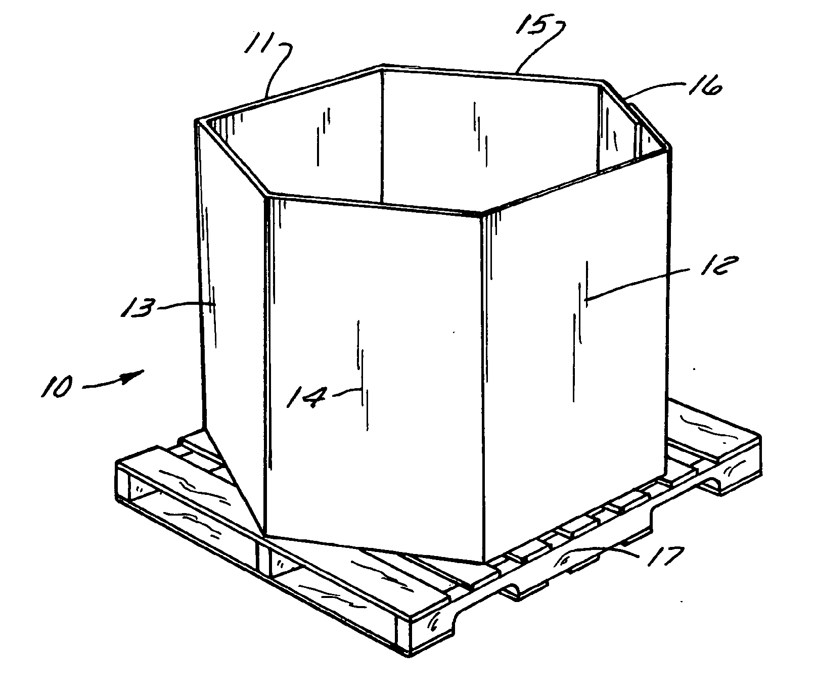
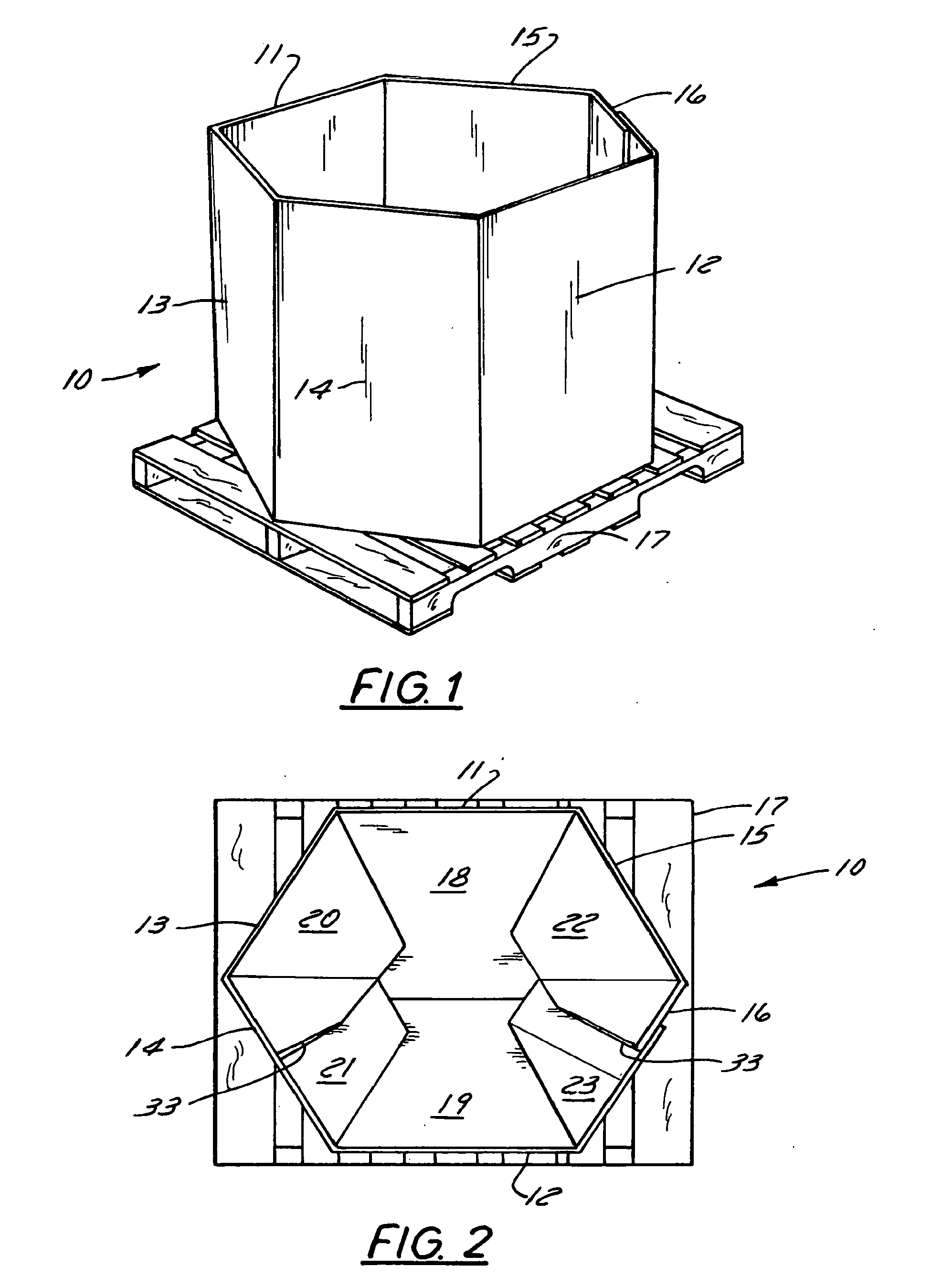
Bulk bin with auto-closing bottom
a bin and bottom technology, applied in the field of large bulk bins, can solve the problems of affecting the storage and handling of bins, affecting the quality of bulk bins, and affecting the storage of bulk bins, and achieve the effect of reducing the difficulty of manual setup of bulk bins with eight sides
- Summary
- Abstract
- Description
- Claims
- Application Information
AI Technical Summary
Benefits of technology
Problems solved by technology
Method used
Image
Examples
second embodiment
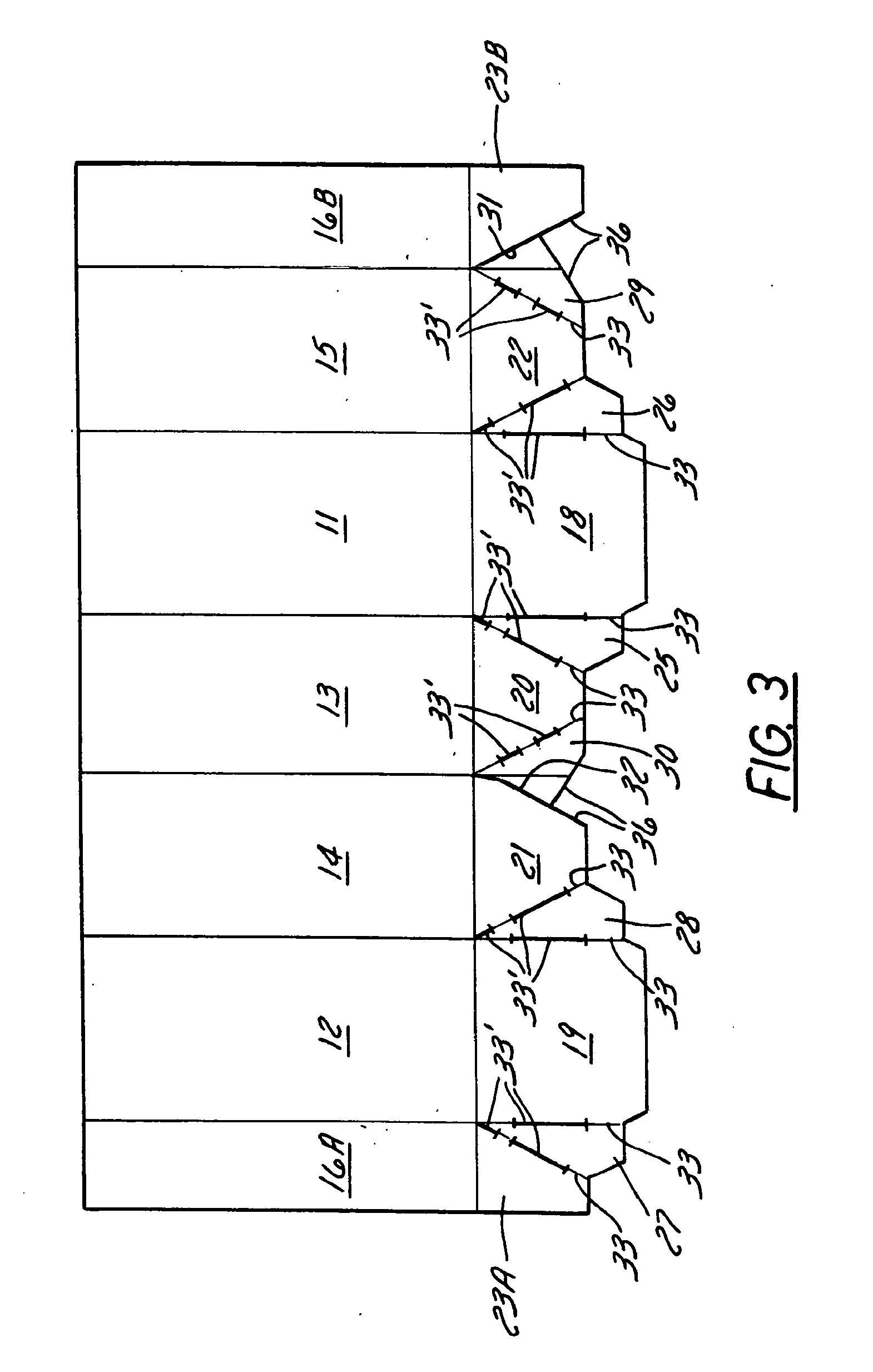
[0040] the bin is indicated generally at 40 in FIG. 14. This embodiment has essentially the same inventive features as the FIG. 3 embodiment, and like parts are indicated by like reference characters. In addition, elliptically shaped creases 41 are formed in the side and end walls, reinforcing tape 42 is placed at predetermined spaced locations in the side and end walls, and the connecting webs 25′, 26′, 27′ and 28′ are crushed as indicated by the shading 43. The elliptical creases are similar to the arrangement shown in applicant's prior U.S. Pat. No. 6,588,651, and help obtain predictable and controlled bulging of the side and end walls. Crushing of the webs removes the natural springiness or memory of the material, resulting in the panels remaining more securely in their folded positions and tending less to spring back out to their unfolded positions.
third embodiment
[0041] the bin is indicated generally at 50 in FIG. 15. This embodiment is substantially the same as the embodiment shown in FIG. 3, and like parts are indicated by like reference characters. The only difference between this embodiment and the FIG. 3 embodiment is that the cuts31′ and 32′ separating the glue flaps 29′ and 30′ from respective adjacent minor bottom flaps are oriented oppositely and are on the opposite sides of the glue flaps from the arrangement shown in FIG. 3, whereby the glue flaps are separated from minor bottom flaps 20′ and 22′ rather than from flaps 21 and 23B as shown in the FIG. 3 embodiment.
[0042]FIG. 16 depicts a fourth embodiment 60 that has some features of the embodiment in FIG. 14, i.e., elliptical creases 41 and reinforcing tape 42 in the sidewalls, and crushed connecting webs 43, and some features from the embodiment of FIG. 15, i.e., the orientation of cuts 31′ and 32′ separating minor flap 22 from adjacent partial bottom flap 23B, and minor flap 20 ...
PUM
 Abstract
Description
Claims
Application Information
 - R&D
- Intellectual Property
- Life Sciences
- Materials
- Tech Scout
- Unparalleled Data Quality
- Higher Quality Content
- 60% Fewer Hallucinations
Browse by: Latest US Patents, China's latest patents, Technical Efficacy Thesaurus, Application Domain, Technology Topic, Popular Technical Reports.
© 2025 PatSnap. All rights reserved.Legal|Privacy policy|Modern Slavery Act Transparency Statement|Sitemap|About US| Contact US: help@patsnap.com


