Adjustable antenna

a technology of adjustable antennas and antennas, applied in the field of adjustable antennas, can solve the problems of insufficient versatility of conventional antennas and inability to provide excellent signal-receiving effects, and achieve the effect of excellent signal-receiving effects

Inactive Publication Date: 2006-06-15
TRANS ELECTRIC
View PDF4 Cites 21 Cited by
  • Summary
  • Abstract
  • Description
  • Claims
  • Application Information

AI Technical Summary

Benefits of technology

[0006] The main objective of the invention is to provide an antenna that can be adjusted to desired angle, direction and height so as to provide an excellent signal-receiving effect. The antenna has a base, a rotating base, a supporting arm, an antenna body and a positioning device. The rotating base is rotatably mounted on the base. The supporting arm is pivotally connected to the rotating base. The antenna body is pivotally attached to the supporting arm. The positioning device is mounted between the supporting arm and the rotating base to support the antenna body at a desired position.

Problems solved by technology

However, the conventional antenna can only be adjusted at angle or direction but cannot be adjusted in height, such that the conventional antenna is not sufficiently versatile in use and cannot provide an excellent signal-receiving effect.

Method used


Image

  • Adjustable antenna
  • Adjustable antenna
  • Adjustable antenna

Examples


Embodiment Construction

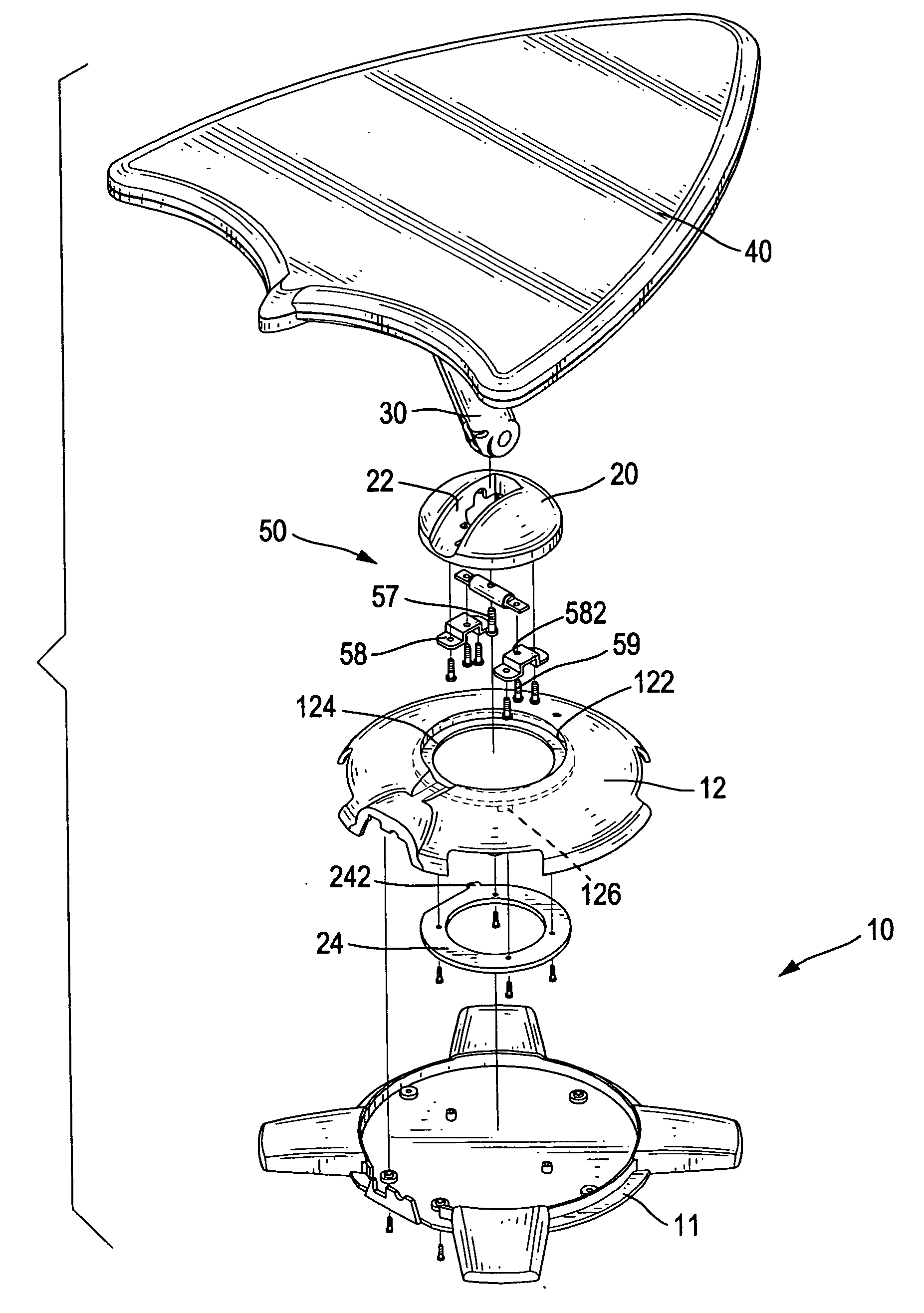
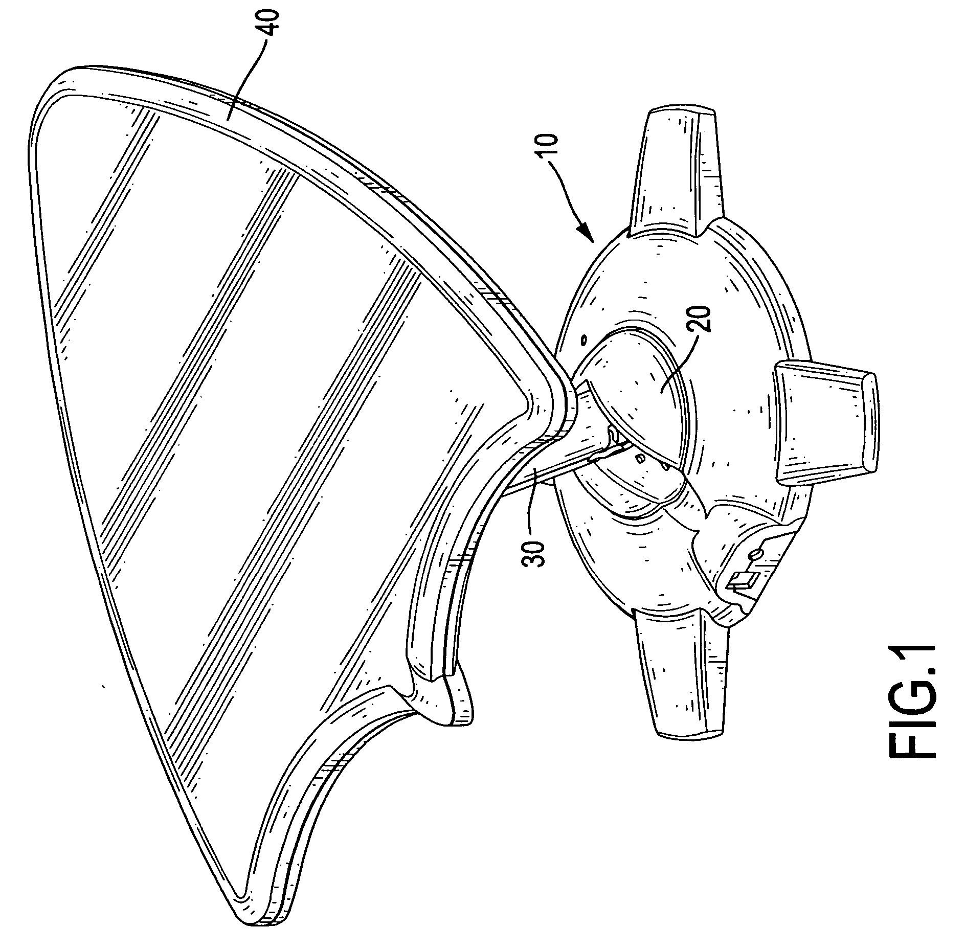
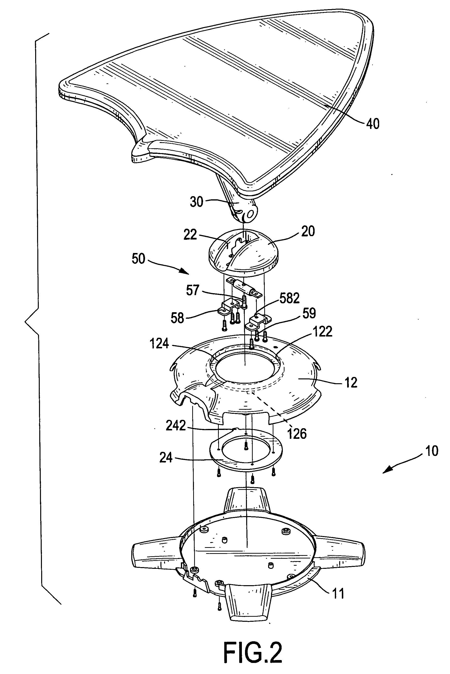
[0015] With reference to FIG. 1 to 4, an antenna in accordance with the present invention comprises a base (10), a rotating base (20), a supporting arm (30), an antenna body (40) and a positioning device (50).

[0016] The base (10) is composed of a bottom plate (11) and a top cover (12) attached to the bottom plate (11). The top cover (12) has an opening (122) with an inner surface defined in the top of the top cover (12). A shoulder (124) is formed on the inner surface of the opening (122).

[0017] The rotating base (20) is rotatably mounted on the base (10). In the preferred embodiment, the rotating base (20) is rotatably mounted inside the opening (122) in the top cover (12) and is supported on the shoulder (124) in the opening (122). The rotating base (20) has a recess (22) defined in the top of the rotating base (20).

[0018] In addition, an annular collar (24) is securely attached to the rotating base (20) to rotate with the rotating base (20) and abuts against the bottom of the ...


PUM


Abstract

An antenna has a base, a rotating base, a supporting arm, an antenna body and a positioning device. The rotating base is rotatably mounted on the base. The supporting arm is pivotally connected to the rotating base. The antenna body is pivotally attached to the supporting arm. The positioning device is mounted between the supporting arm and the rotating base to support the antenna body at a desired position. Accordingly, the antenna body can be adjusted to a desired angle, direction and height so as to provide an excellent signal-receiving effect.

Description

BACKGROUND OF THE INVENTION [0001] 1. Field of the Invention [0002] The present invention relates to an antenna, and more particularly to an adjustable antenna to provide an excellent signal-receiving effect. [0003] 2. Description of Related Art [0004] Indoor television antennas are connected to televisions for receiving television signals transmitted from television stations. To improve the signal-receiving effect, an antenna is always adjustable to try to achieve optimum reception of those signals and so acquire the best TV picture. However, the conventional antenna can only be adjusted at angle or direction but cannot be adjusted in height, such that the conventional antenna is not sufficiently versatile in use and cannot provide an excellent signal-receiving effect. [0005] To overcome the shortcomings, the present invention tends to provide an antenna to mitigate or obviate the aforementioned problems. SUMMARY OF THE INVENTION [0006] The main objective of the invention is to pro...

Claims


Application Information

Patent Timeline
Patent Type & Authority Applications(United States)
IPC IPC(8): H01Q3/02
CPCH01Q3/04H01Q3/08
Inventor WANG, CHENG-SI
Owner TRANS ELECTRIC
Why Eureka
Try Eureka