Integrated GNSS deformation monitoring device

A deformation monitoring and equipment technology, applied in the GNSS field, can solve the problems affecting the quality of monitoring, the difficulty of on-site installation, and the time spent on debugging, so as to save installation time, reduce the difficulty of debugging, and avoid installation and debugging.

Inactive Publication Date: 2019-04-16
HUBEI CHUHANG ELECTRONICS TECH CO LTD
View PDF4 Cites 9 Cited by
  • Summary
  • Abstract
  • Description
  • Claims
  • Application Information

AI Technical Summary

Problems solved by technology

[0003] For the existing deformation monitoring equipment using GNSS technology, each component is transported to the monitoring site, and the components are assembled on site. During the assembly process, the monitoring equipment needs to be debugged, because the geographical location and environment of each place are different. , debugging takes a lot of time
[0004] That is to say, the existing deformation monitoring equipment of GNSS technology has the following defects on site: each part is designed independently, the on-site installation is difficult, and professional personnel are required to assemble; the independently installed equipment is responsible for debugging, and the debugging is not allowed to affect the quality of monitoring

Method used


Image

  • Integrated GNSS deformation monitoring device
  • Integrated GNSS deformation monitoring device

Examples


Embodiment Construction

[0027] In order to make the object, technical solution and advantages of the present invention clearer, the present invention will be further described in detail below in conjunction with the accompanying drawings and embodiments. It should be understood that the specific embodiments described here are only used to explain the present invention, not to limit the present invention. In addition, the technical features involved in the various embodiments of the present invention described below can be combined with each other as long as they do not constitute a conflict with each other.

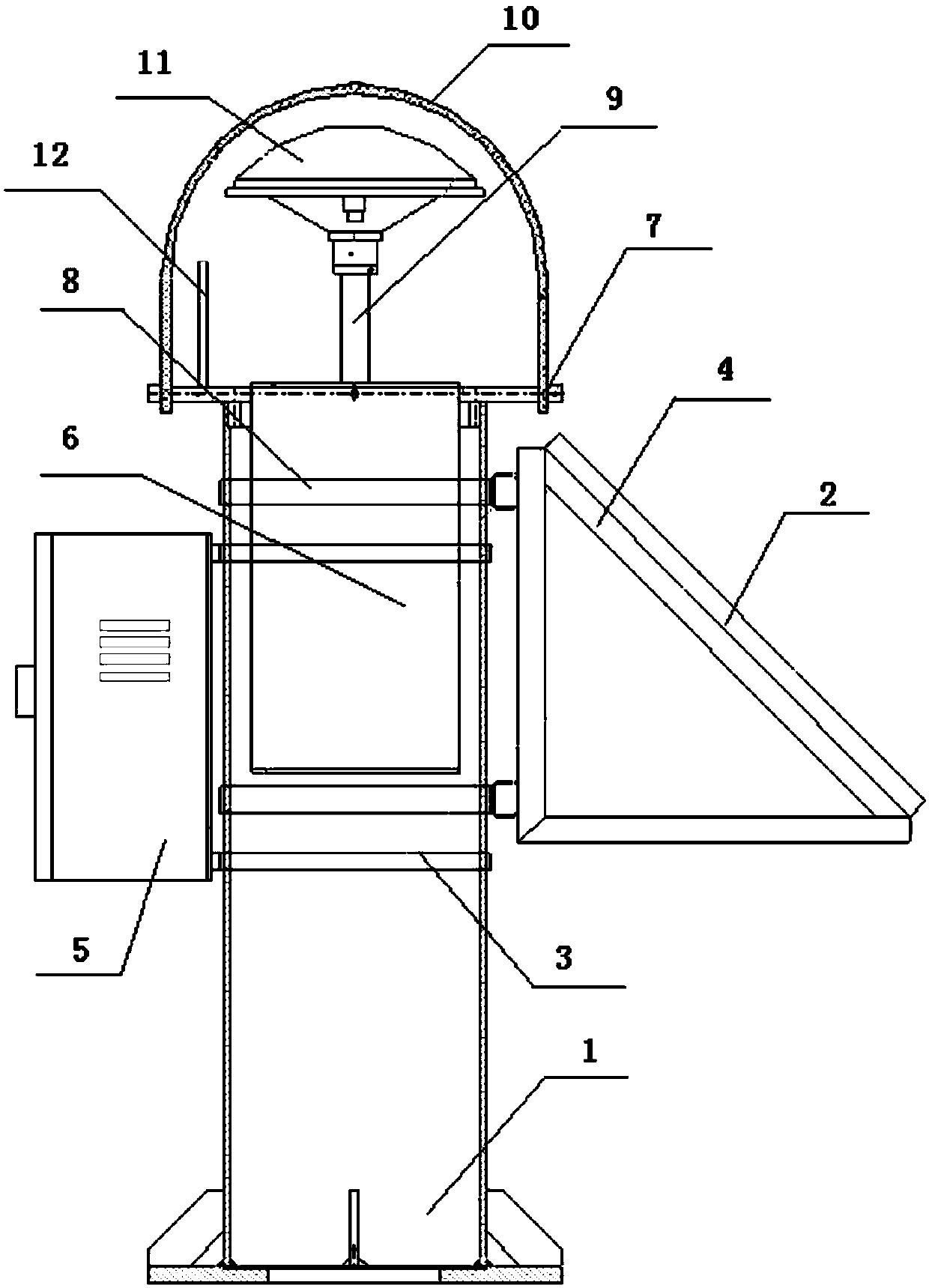
[0028] figure 1 It is a schematic structural diagram of an integrated GNSS deformation monitoring device in an embodiment of the present invention. Such as figure 1 As shown, the GNSS deformation monitoring device of the present invention includes an observation pier, a GNSS receiver 6, a mounting plate 7, a GNSS antenna 11, a GNSS antenna mounting bracket 9, a radome 10, a solar panel 2, a mo...


PUM


Abstract

The invention discloses an integrated GNSS deformation monitoring device. The integrated GNSS deformation monitoring device comprises an observation pillar, a GNSS antenna (11) and a GNSS receiver (6), wherein the observation pillar comprises an observation cylinder body and an observation base (1), and an integrated observation structure is arranged on the top of the observation cylinder body; and the integrated observation structure comprises an installation disc (7) and an antenna cover (10) which together form hemispherical installation space, the GNSS antenna (11) is a disc-shaped activeantenna which is arranged in the right middle of the installation space, a GNSS antenna installation support (9) used for fixing the GNSS antenna (11) is arranged between the GNSS antenna (11) and theinstallation disc (7), the GNSS receiver (6) used for receiving signals from the GNSS antenna (11) is arranged inside the observation cylinder body, and holders which can rotate around the observation cylinder body are arranged on the outer side of the observation cylinder body and are fixedly provided with a rainproof case (5) and a solar cell panel (2). The integrated GNSS deformation monitoring device makes rapid installation and debugging possible, so that installation time and debugging time of the monitoring device are greatly saved.

Description

technical field [0001] The invention belongs to the technical field of GNSS, and more specifically relates to integrated GNSS deformation monitoring equipment. Background technique [0002] In the field of construction, it is usually necessary to monitor the deformation of the roof of the building through GNSS (Global Navigation Satellite System), by setting monitoring points in key parts of the main building, including GPS in the United States, Glonass in Russia, Galileo in Europe, and Beidou in China satellite navigation system. With the development of science and technology, GNSS technology is used more and more as a high-precision deformation monitoring method, which can be applied to reservoir dam monitoring, deep foundation pit monitoring, roadbed monitoring of roads and railways, mine safety monitoring, high-rise building tilt Monitoring and power tower monitoring and other fields. [0003] For the existing deformation monitoring equipment using GNSS technology, eac...

Claims


Application Information

Patent Timeline
Patent Type & Authority Applications(China)
IPC IPC(8): G01B7/16G01S19/14
CPCG01B7/16G01S19/14
Inventor 周浩杨文建董拉
Owner HUBEI CHUHANG ELECTRONICS TECH CO LTD
Why Eureka
Try Eureka