
Method of compensating missing nozzle and printer using the same

a technology of missing nozzles and printers, applied in the field of inkjet printers, can solve the problems of inability to compensate the image corresponding to the missing nozzle, inability to compensate the missing nozzle of other colors, and inability to compensate the black missing nozzl

Inactive Publication Date: 2006-06-15
S PRINTING SOLUTION CO LTD
View PDF5 Cites 40 Cited by
  • Summary
  • Abstract
  • Description
  • Claims
  • Application Information

AI Technical Summary

Benefits of technology

[0014] In order to solve the foregoing and / or other problems, the present general inventive concept provides a method of compensating a missing nozzle of a printer, and a printer using the same so that an appropriate image quality can be maintained by compensating a region, at which the missing nozzle should print, using at least one nozzle adjacent to the missing nozzle.

Problems solved by technology

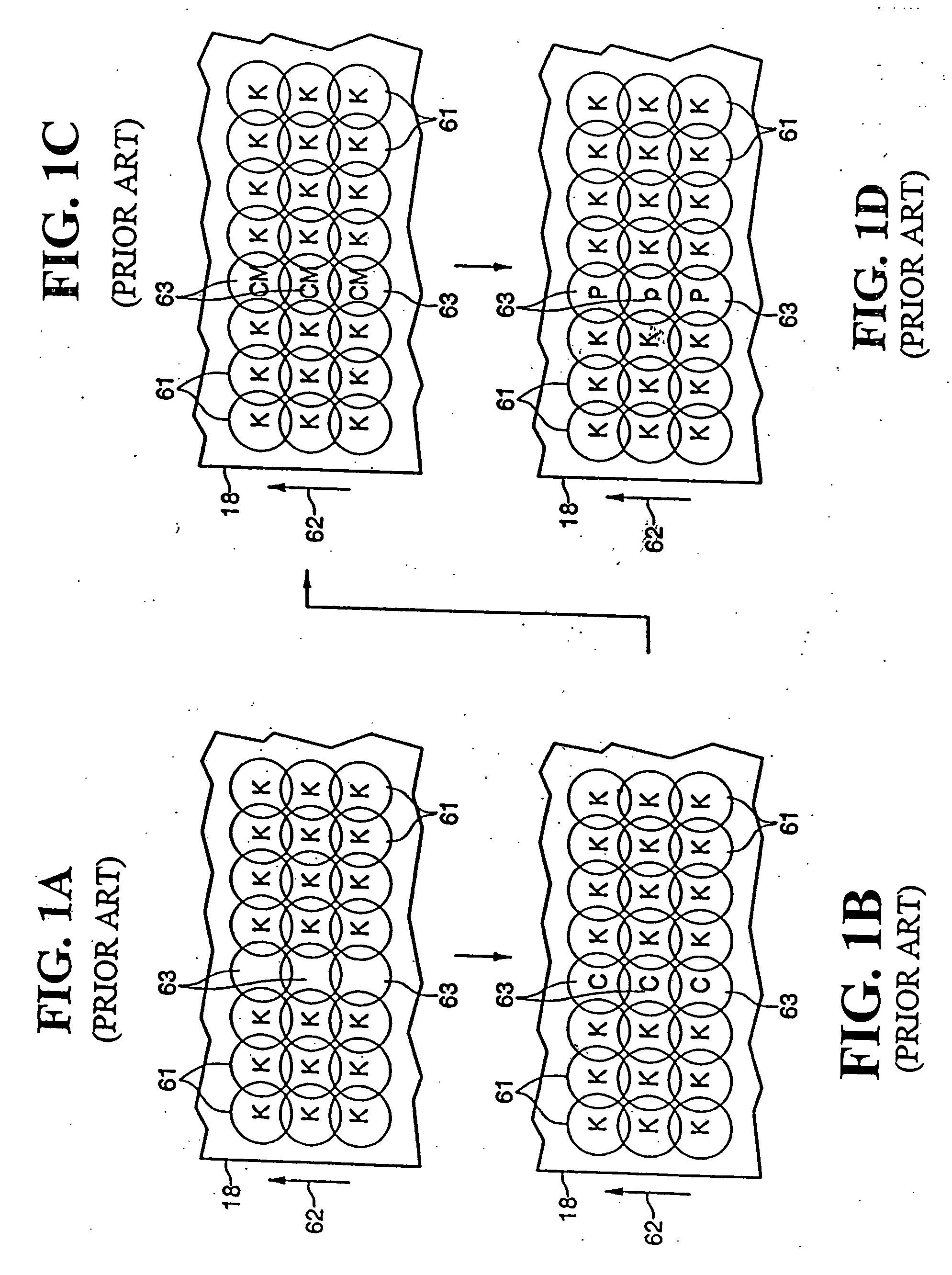
However, in case of the page printer, when the missing nozzle is generated, it is impossible to compensate the image corresponding to the missing nozzle using the shingling method like the shuttle printer, since the printer head is stationary.
However, since the method forms the black color through the combination of three colors (cyan, magenta and yellow), to compensate only the black missing nozzle, it is impossible to compensate missing nozzles of other colors.
In addition, in the case that the cyan, magenta and yellow nozzles corresponding to the black missing nozzle are already operated when the black missing nozzle should be compensated, or any one of the cyan, magenta and yellow nozzles is out of order, it is impossible to compensate the black missing nozzle.
However, when the composite color image is printed, since the cyan, magenta and yellow nozzles are likely to be operated, when any one of the nozzles is operated, it is impossible to generate black dots corresponding to the black missing nozzle.

Method used


Image

  • Method of compensating missing nozzle and printer using the same
  • Method of compensating missing nozzle and printer using the same
  • Method of compensating missing nozzle and printer using the same

Examples


Embodiment Construction

[0030] Reference will now be made in detail to the embodiments of the present general inventive concept, examples of which are illustrated in the accompanying drawings, wherein like reference numerals refer to the like elements throughout. The embodiments are described below in order to explain the present general inventive concept by referring to the figures.

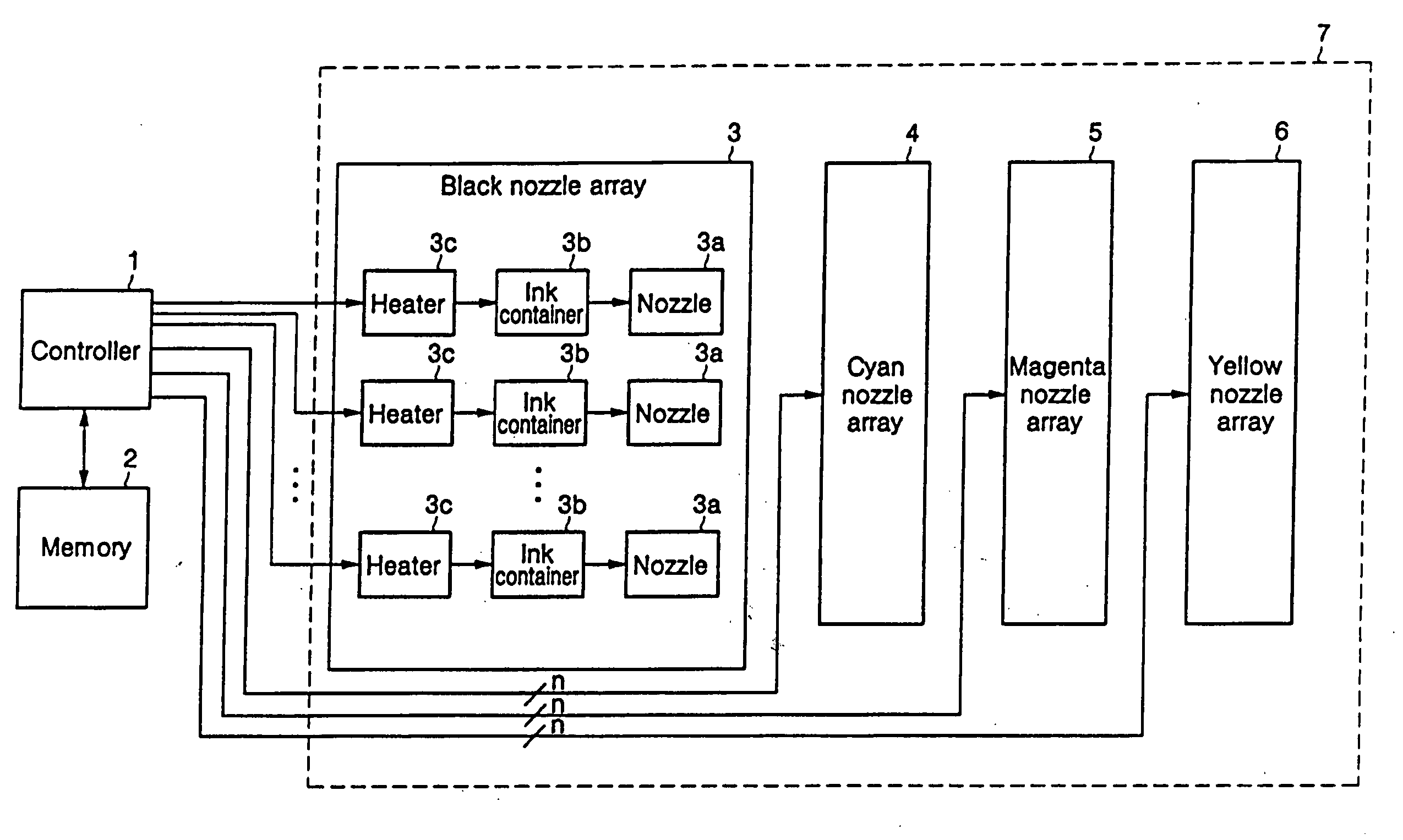
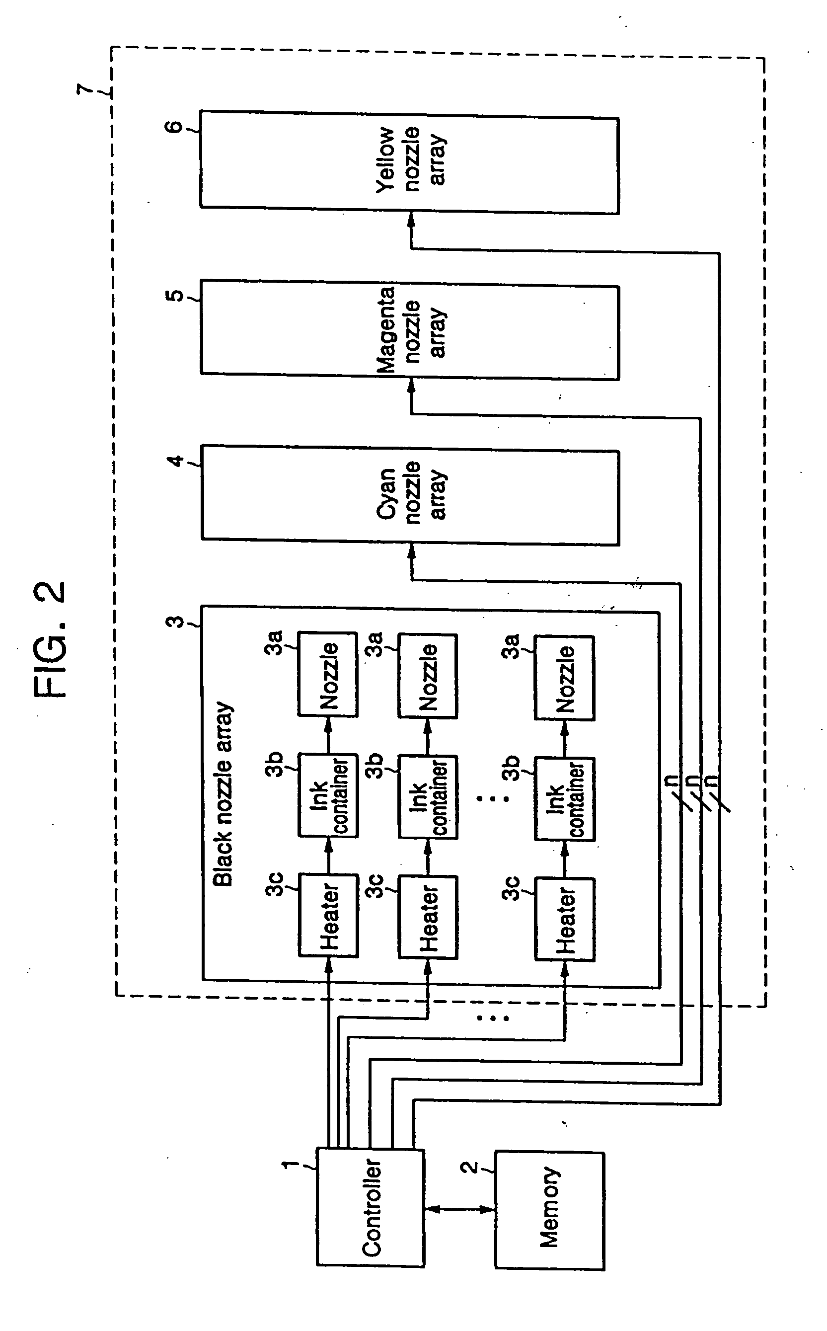
[0031]FIG. 2 is a view illustrating an inner block diagram of a printer according to an embodiment of the present general inventive concept.

[0032] Referring to FIG. 2, the printer includes a controller 1, a memory 2, and a printer head 7, and the printer head 7 includes a plurality of nozzle arrays 3, 4, 5 and 6 corresponding to black, cyan, magenta and yellow, respectively. Each of the nozzle arrays 3, 4, 5 and 6, for example, the black nozzle array 3 includes a plurality of nozzles 3a, a plurality of heaters 3c corresponding to the respective nozzles 3a, and a plurality of ink containers 3b corresponding to the respective n...


PUM


Abstract

A method of compensating a missing nozzle of a printer and a printer using the same. The method includes determining adjacent nozzles corresponding to the missing nozzle, and compensating the missing nozzle by generating dots having an increased size through the adjacent nozzles and generating dots having a normal size through other nozzles when the missing nozzle is generated in the nozzles performing a printing operation. Therefore, it is possible to compensate operations of all color nozzles as well as the black nozzle. As a result, the method of compensating the missing nozzle of the printer compensates operations of the missing nozzle when an image having a composite color is printed as well as when the black image is printed. In addition, it is possible to maintain appropriate image quality by compensating the operation of the missing nozzle through other adjacent nozzles even when a portion of the adjacent nozzles is out of order, since the number of the adjacent nozzles is larger.

Description

CROSS-REFERENCE TO RELATED APPLICATIONS [0001] This application claims the benefit under 35 U.S.C. §119 of Korean Patent Application No. 2004-105908, filed Dec. 14, 2004, the disclosure of which is hereby incorporated herein by reference in its entirety. BACKGROUND OF THE INVENTION [0002] 1. Field of the Invention [0003] The present general inventive concept relates to an inkjet printer, and more particularly, to a method of compensating a missing nozzle, and a printer using the same to maintain an appropriate image quality by compensating an operation of the missing nozzle through adjacent nozzles. [0004] 2. Description of the Related Art [0005] An inkjet printer is generally classified into a shuttle (or serial) printer and a page printer based on a method driving a printer head. The shuttle printer prints an image as the printer head laterally moves, and the page printer prints an image with the printer head being fixed in a lateral direction to media. [0006] In the case of the s...

Claims


Application Information

Patent Timeline
Patent Type & Authority Applications(United States)
IPC IPC(8): B41J29/38
CPCB41J2/2139B41J2/07B41J2/3556B41J2/38B41J29/393
Inventor KIM, TAE-KYUNJUNG, MYUNG-SONG
Owner S PRINTING SOLUTION CO LTD
Learn More