Image display system and image display device

a display system and image technology, applied in the field of image display systems, can solve the problems of inability to provide appropriate image quality to users, failure to carry out appropriate gradation display processes,

Inactive Publication Date: 2014-07-08
NEC DISPLAY SOLUTIONS LTD
View PDF17 Cites 0 Cited by
  • Summary
  • Abstract
  • Description
  • Claims
  • Application Information

AI Technical Summary

Benefits of technology

[0019]It is an object of the present invention to provide a technique for supplying appropriate image quality to a user.

Problems solved by technology

Therefore, depending on the computer system 100 to be connected to the display device 110, the gain value and bias value of the input analog image signal are set by using only the stable area data which has been subjected to influences from a ringing phenomenon, resulting in a failure to carry out an appropriate gradation displaying process in some cases.
This makes it impossible to provide appropriate image quality to the user.

Method used


Image

  • Image display system and image display device
  • Image display system and image display device
  • Image display system and image display device

Examples


first embodiment

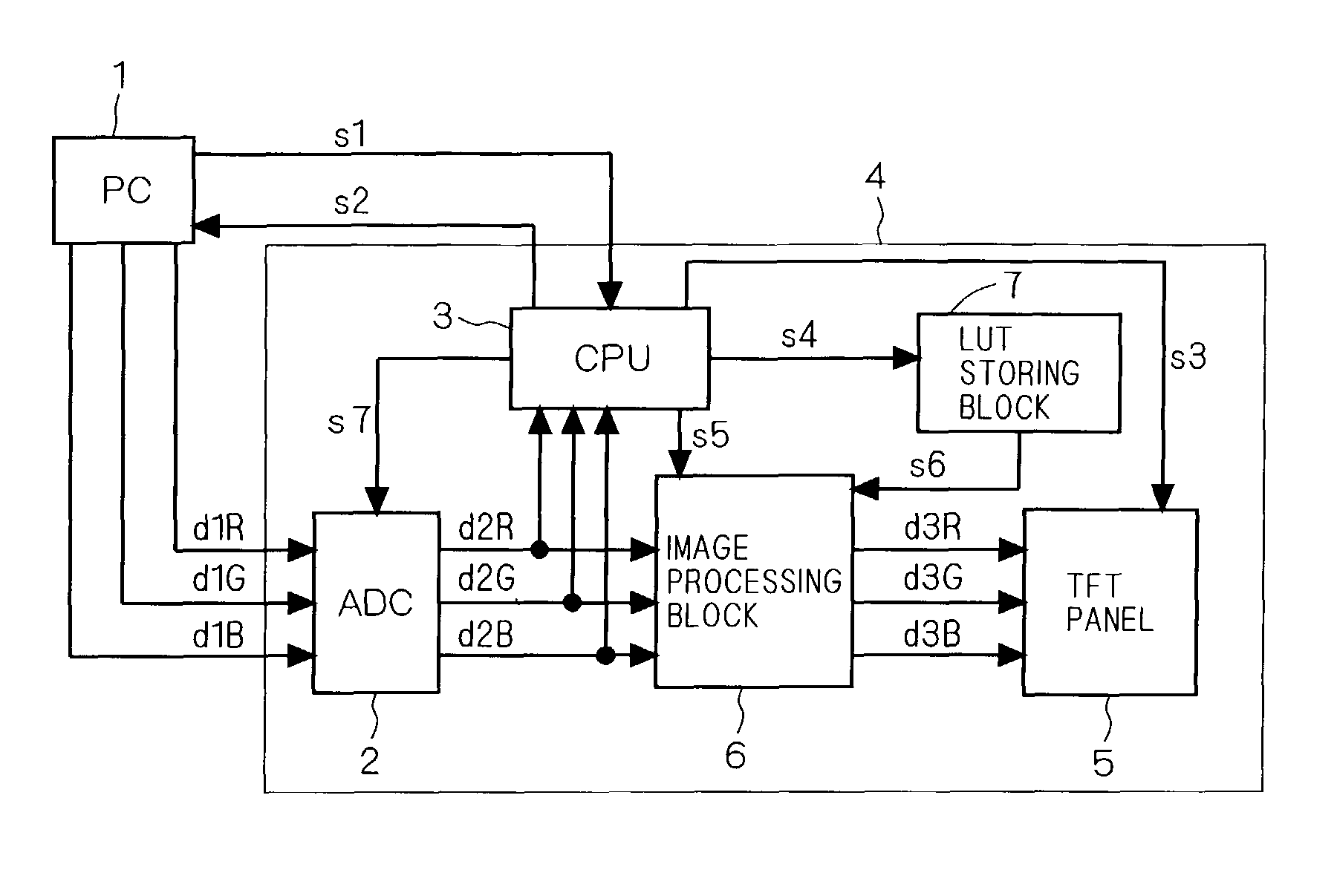
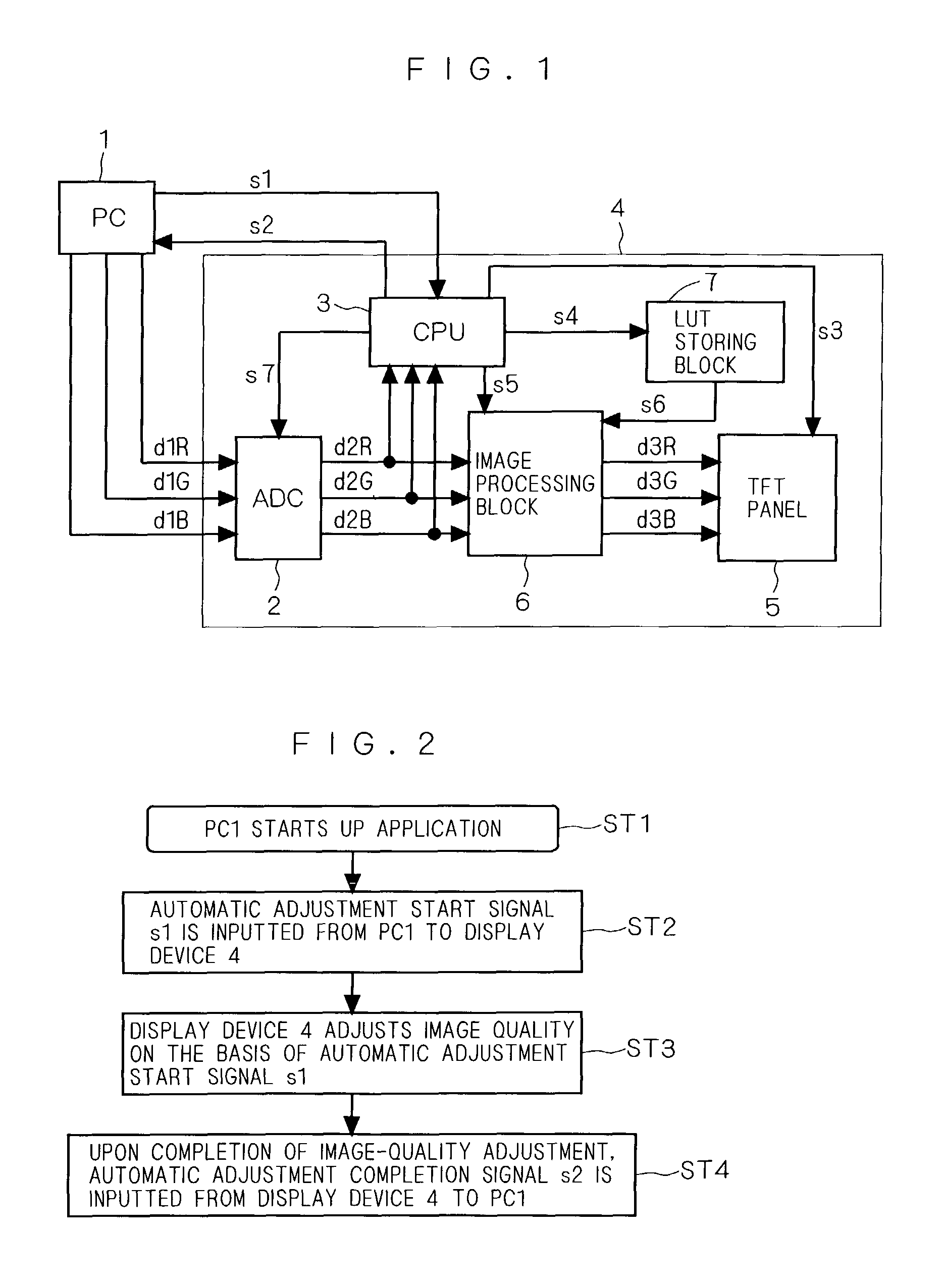
[0036]FIG. 1 is a block diagram showing a configuration of an image display system according to a first embodiment of the present invention, and this also serves as a block diagram showing a configuration of an image display system according to a second embodiment, which will be described later. As shown in FIG. 1, the image display system according to the first embodiment is provided with: a personal computer (hereinafter, referred to as “PC”) 1 which executes a plurality of pieces of application software (hereinafter, simply referred to as “application”) and outputs analog image signals d1R, d1G and d1B that correspond to the respective applications; and an image display device 4 (hereinafter, simply referred to as “display device 4”) which displays an image on the basis of the analog image signals d1R, d1G and d1B. Here, the analog image signals d1R, d1G and d1B outputted by the PC1, are color signals corresponding to red (R), green (G) and blue (B) in this order, and these analo...

second embodiment

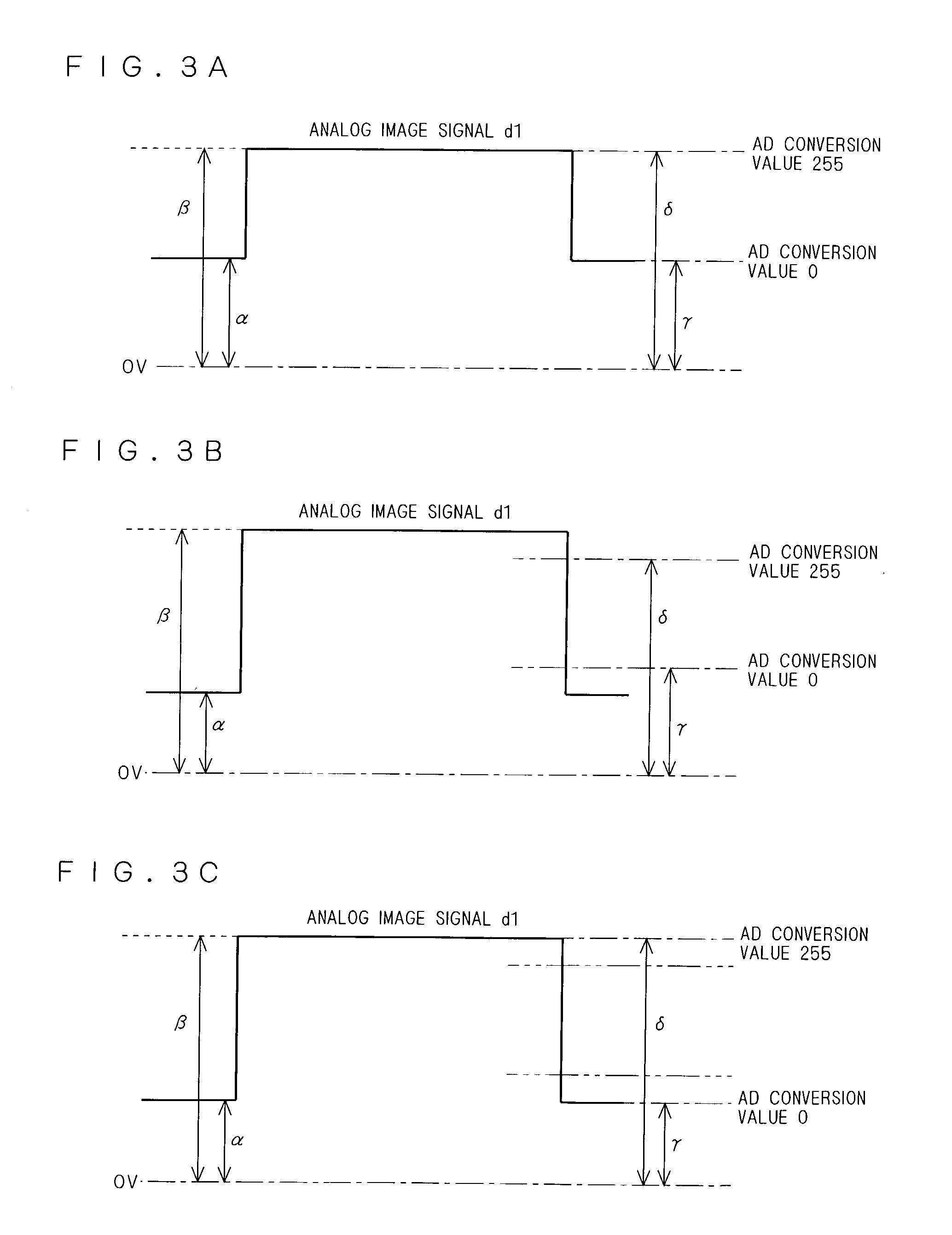
[0049]Next, referring again to FIG. 1, an image display system according to the second embodiment will be described. In the image display system according to the second embodiment, the analog input range of the ADC2 is further adjusted by using a gradation adjusting signal s7 which is not used in the image display system according to the above-described first embodiment. As described above, in order to gradation-display an image appropriately, a gradation-adjusting process for matching the signal level of the analog image signal d1 with the analog input range of the ADC2 is required. In the second embodiment, this gradation adjustment is carried out by changing the analog input range of the ADC2. Here, the other configurations are the same as those of the image display system according to the above-described first embodiment, Therefore, none of description therefor will be given.

[0050]FIGS. 3A, 3B and 3C show the relationship between the signal level of the analog image signal d1 an...

third embodiment

[0066]FIG. 6 is a block diagram showing a configuration of an image display system according to a third embodiment. In the image display system according to the above-described second embodiment, the gradation adjustment is carried out by changing the analog input range of the ADC2. However, in the image display system according to the third embodiment, the gradation adjustment is carried out by changing the signal level of the analog image signal d1. With respect to the configuration thereof, a preamplifier 10 is further provided to the image display system according to the first embodiment, and in place of the gradation adjusting signal s7 outputted to the ADC2, the CPU3 outputs a gradation adjusting signal s17 to the preamplifier 10 so that a gradation adjusting process is carried out by changing the signal level of the analog image signal d1.

[0067]As shown in FIG. 6, the analog image signal d1, which is outputted from the PC1, is inputted to the preamplifier 10, and the preampli...


PUM


Abstract

The present invention provides a technique for supplying appropriate image quality to a user. Upon executing an application, a PC1 outputs an automatic adjustment start signal s1 which is information relating to image quality required for the application, and on the basis of the automatic adjustment start signal s1, a display device 4 adjusts the image quality. Thus, it is possible to display an image with image quality suitable for each of the applications without causing any time-consuming manual operations by the user. Consequently, it is possible to provide appropriate image quality to the user.

Description

BACKGROUND OF THE INVENTION[0001]1. Field of the Invention[0002]The present invention relates to an image display system for displaying an image on the basis of an image signal sent from a computer, and an image display device.[0003]2. Description of the Background Art[0004]FIG. 8 is a block diagram showing a configuration of a conventional image display system. As shown in FIG. 8, the conventional image display system is provided with a computer system 100 and a display device 110 connected to the computer system 100. The display device 110 has a preamplifier 120, an analog / digital converter (hereinafter, referred to as “A / D converter”) 130, a microcomputer 140, a PLL (Phase Locked Loop) unit 150, a graphic controller 160 and a liquid crystal display panel 170.[0005]The computer system 100 outputs an analog image signal composed of color signals of red (R), green (G) and blue (B) to the preamplifier 120, and outputs a horizontal synchronous signal H and a vertical synchronous signa...

Claims


Application Information

Patent Timeline
Patent Type & Authority Patents(United States)
IPC IPC(8): G06F3/153G09G5/10G09G3/20G09G3/36G09G5/00
CPCG09G5/005G09G3/3648G09G5/006G09G2320/0271G09G2320/0673
Inventor TOBIYA, AKIRA
Owner NEC DISPLAY SOLUTIONS LTD
Why Eureka
Try Eureka