Image generating apparatus and control method therefor

a technology control method, which is applied in the field of image generating apparatus, can solve the problems of long time needed to generate acoustic wave image, inability to meet the needs of image quality, etc., and achieve the effect of efficient work flow

Inactive Publication Date: 2019-09-03
CANON KK
View PDF6 Cites 0 Cited by
  • Summary
  • Abstract
  • Description
  • Claims
  • Application Information

AI Technical Summary

Benefits of technology

[0009]The present invention has been achieved in view of the foregoing problem. An object of the present invention is to provide an efficient work flow by generating an image having an appropriate image quality in accordance with a test situation.
[0014]According to the present invention, by generating an image having an appropriate image quality in accordance with a test situation, an efficient work flow can be provided.

Problems solved by technology

However, in the invention described above, the time spent to generate an acoustic wave image and the image quality may not necessarily be appropriate.
When a high-quality acoustic wave image is generated, a long time is needed to generate the acoustic wave image.
Consequently, the acquisition of a test result may be delayed longer than necessary.
This may result in an inefficient diagnostic work flow depending on the settings of the time spent to generate an acoustic wave image and the image quality.

Method used


Image

  • Image generating apparatus and control method therefor
  • Image generating apparatus and control method therefor
  • Image generating apparatus and control method therefor

Examples


embodiment 1

[0035][Embodiment 1]

[0036](System Configuration)

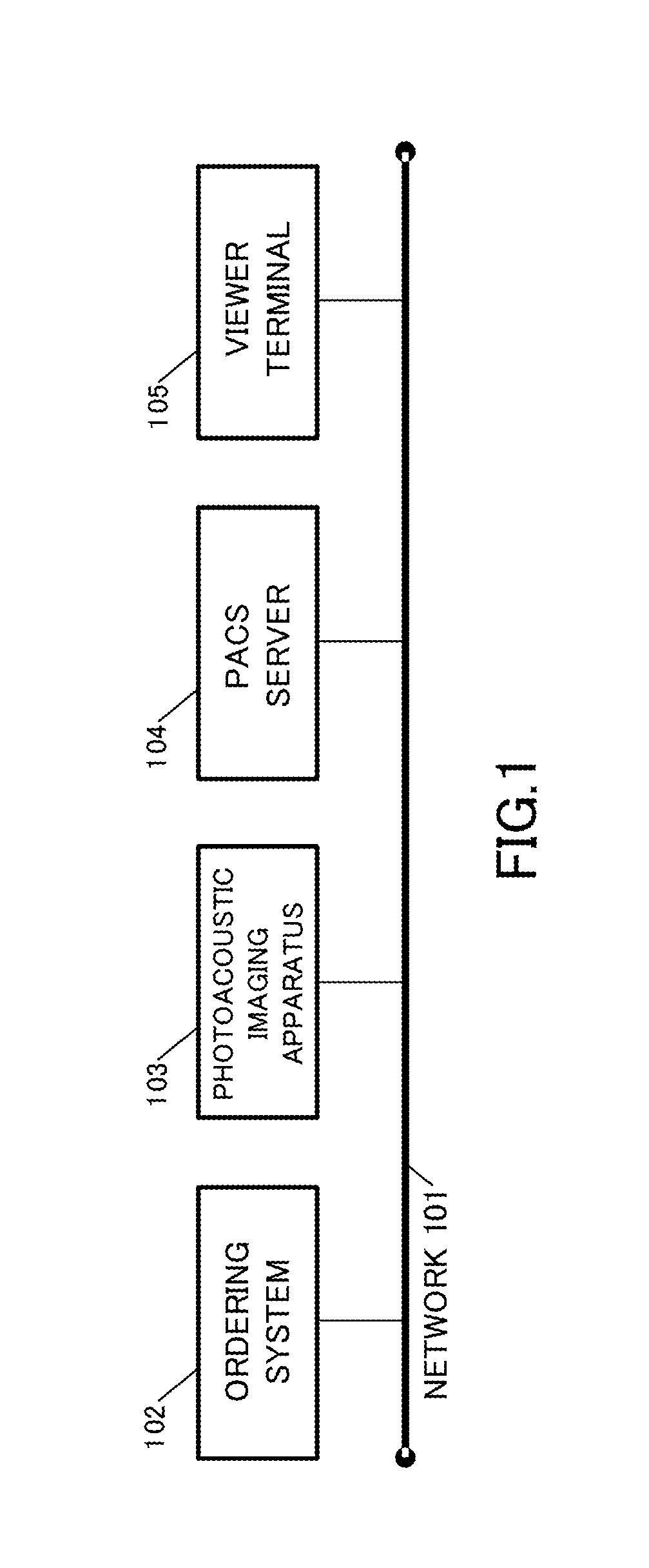
[0037]FIG. 1 is a view showing a network configuration of a whole system. The following is a description of each of the components in FIG. 1. A network 101 is a computer network connecting individual nodes 102 to 105 to each other. The network 101 shown in FIG. 1 is a bus-type network, but is not limited thereto. The network 101 may also be a network of another type.

[0038]Each of the nodes 102 to 105 transmits / receives an order and an image to / from another node through the network 101.

[0039]The ordering system 102 has the function of issuing an order to a photoacoustic imaging apparatus 103. The order is information for requesting a test of the photoacoustic imaging apparatus 103. The ordering system 102 includes a computer terminal. A medical doctor inputs information related to a test for a patient from the computer terminal. The computer terminal receives the input of the information related to the order from the medical doctor who ...

embodiment 2

[0128][Embodiment 2]

[0129]In Embodiment 2, processing is performed on the basis of the order input by the user.

[0130]When test items cannot be specified on the basis of the patient information such as when, e.g., the patient is an emergency outpatient, the ordering system 102 cannot set the order on the basis of the patient information. As a result, the ordering system 102 requests the medical doctor to input the order. Note that the ordering system 102 may also set a part of the order even when the patient is an emergency outpatient.

[0131]The overall configuration of the system including the photoacoustic imaging apparatus and the content of the processing in Embodiment 2 are the same as in FIG. 1, except for the points shown below.

[0132]When the patient information 404 is “EMERGENCY”, the ordering system 102 requests the imaging technologist to input the protocol 401. The order acquiring unit 207 receives the protocol 401 input via the input unit 205.

[0133]Note that, when an emerg...


PUM


Abstract

An image generating apparatus comprises an information acquiring unit that acquires request information including information representing a viewing time and information representing image qualities; a control unit that sets the image qualities to the image qualities specified by the request information when the plurality of images can be generated with the image qualities specified by the request information before the viewing time passes, and sets the image qualities by changing the image qualities from the image qualities specified by the request information, otherwise; and a generating unit that generates the plurality of images with the image qualities set by the control unit.

Description

BACKGROUND OF THE INVENTION[0001]Field of the Invention[0002]The present invention relates to an image generating apparatus and a control method therefor.[0003]Description of the Related Art[0004]Mainly in the medical field, active research has been conducted on a photoacoustic apparatus which obtains information related to an object on the basis of acoustic waves (photoacoustic waves) generated by irradiating the object with light. By repeatedly irradiating the object with light at varied positions and reconstructing acquired photoacoustic signals, three-dimensional information of the object can be obtained. In addition, it has become prevalent to use the three-dimensional information acquired on the basis of the photoacoustic waves for diagnosis.[0005]There is a trade-off relationship between the time spent to generate an acoustic wave image and the image quality. In other words, as more time is spent to generate the acoustic wave image, the image quality can be increased. The sam...

Claims


Application Information

Patent Timeline
Patent Type & Authority Patents(United States)
IPC IPC(8): A61B5/00G06T11/00G16H40/63G16H10/60G16H30/20G06F3/0484A61B5/145
CPCA61B5/0095G06F3/04847G16H40/63G16H10/60G06T11/005G16H30/20G06T11/003A61B5/4312G06T2200/24G06T2211/40A61B5/14532A61B5/14542
Inventor NOJIRI, YUSUKEMIYAZAWA, NOBU
Owner CANON KK
Why Eureka
Try Eureka