Coil element selection device for selecting elements of a receiver coil array of a magnetic resonance imaging device

Inactive Publication Date: 2009-12-10
KONINKLIJKE PHILIPS ELECTRONICS NV
View PDF8 Cites 4 Cited by
  • Summary
  • Abstract
  • Description
  • Claims
  • Application Information

AI Technical Summary

Benefits of technology

[0035]The inventive SENSE-optimized element selection is based on an actual distribution of e.g. coil sensitivities, wherein an optimal sense unfolding in e.g. an unforeseen use of coils (for example rotated placement) may be achieved. Furthermore the knowledge of the geometrical arrangement of the sensor elements (e.g. coils) is not nec

Problems solved by technology

The disadvantage of the coil location-based selection approach is that the coil positions must be known or must be measured.
Manual selection might be impaired by

Method used


Image

  • Coil element selection device for selecting elements of a receiver coil array of a magnetic resonance imaging device
  • Coil element selection device for selecting elements of a receiver coil array of a magnetic resonance imaging device
  • Coil element selection device for selecting elements of a receiver coil array of a magnetic resonance imaging device

Examples


Embodiment Construction

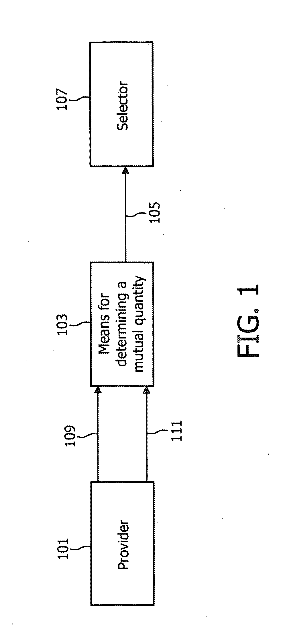
[0045]FIG. 1 shows a block diagram of the sensor selection device comprising a provider 101, a means 103 for determining a mutual quantity 105 and a selector 107. The provider provides a first characteristic property 109 of a first sensor (not shown in FIG. 1) and a second characteristic property 111 of a second sensor (not shown in FIG. 1).

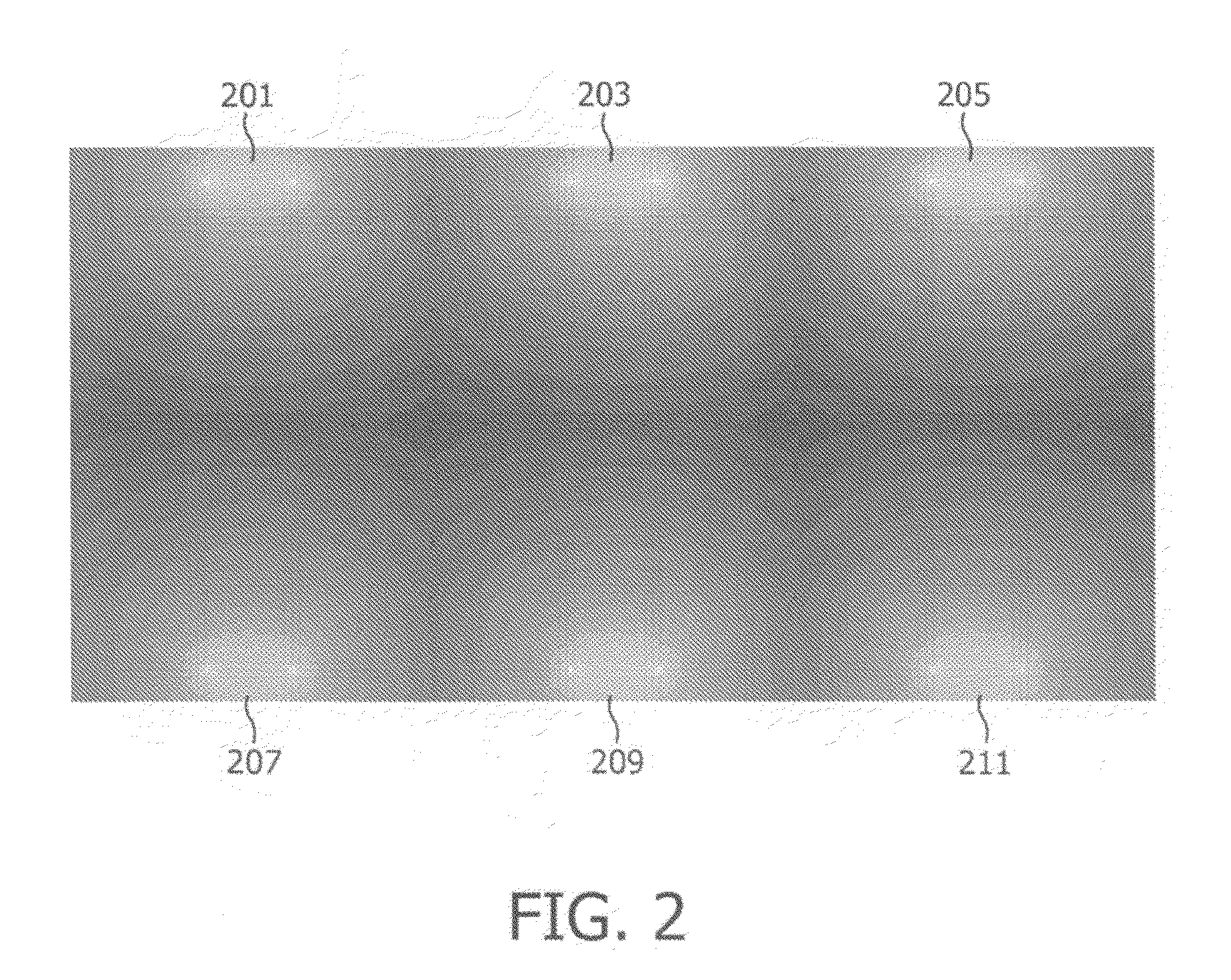
[0046]FIG. 2 shows a calculated coil sensitivity map of two arrays of three elements. A first array comprises the elements 201, 203 and 205. The second array comprises the elements 207, 209 and 211.

[0047]FIG. 3 shows a contour 213 of a subject to be scanned (e.g. a patient) and a scan volume 215 (region of interest, predetermined scan volume). For example, the elements 207 and 209 which are arranged outside the scan volume 215 may be used for sensing, since their sensitivity extends within the scan volume.

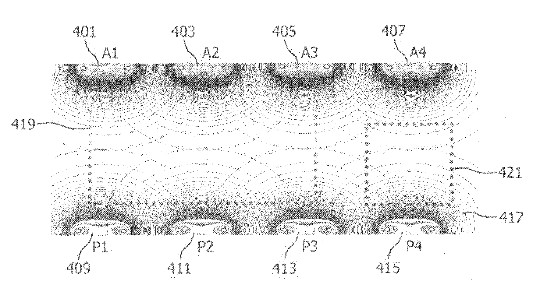
[0048]FIG. 4 demonstrates the inventive region of interest based sensor element selection. In this embodiment, the magnetic resonance imaging d...


PUM


Abstract

The present invention provides a sensor selection device for selecting sensor elements of a magnetic resonance imaging device, the sensor selection device comprising a provider for providing a first characteristic property (601) of a first sensor element (603) within a predetermined scan volume and for providing a second characteristic property (605) of a second sensor element (607) within the predetermined scan volume (215), a means for determining a mutual quantity from the first characteristic property (601) and from the second characteristic property (605), and a selector for selecting or for excluding the first sensor element (601) or the second sensor element (601) based on the mutual quantity.

Description

FIELD OF THE INVENTION[0001]The present invention is directed to the field of magnetic resonance imaging devices comprising sensor elements for acquiring magnetic resonance signals.[0002]Magnetic resonance imaging devices may acquire imaging data using parallel imaging with an increasing number of sensor elements, e.g. coil elements and data acquisition channels. In the early 90's, usually only one channel output was used. In the mid-nineties, multi-channel-acquisition was introduced, so that, at present, 16, 32 or 90 channel acquisitions are achievable.[0003]In the recent past, typically four or six channels were employed, so that an operator of a magnetic resonance imaging (MRI) system could make a selection of sensor elements used for scanning manually. However, when using MRI systems with over 50 sensor elements (e.g. coil elements) connected with each other, wherein about 30 sensor elements are arranged within the field of view at the same time, the selection has to be automate...

Claims


Application Information

Patent Timeline
IPC IPC(8): G01R33/44
CPCG01R33/3415
Inventor BENSCHOP, FRANCISCUS JOHANES MARIA
Owner KONINKLIJKE PHILIPS ELECTRONICS NV
Why Eureka
Try Eureka