Retaining assembly

Inactive Publication Date: 2006-07-06
TUMI INC
View PDF2 Cites 2 Cited by
  • Summary
  • Abstract
  • Description
  • Claims
  • Application Information

AI Technical Summary

Benefits of technology

[0005] For example, in one exemplary embodiment of the present invention, a retaining assembly includes a first portion adapted to be attached to a strap; a second portion capable of being secured to the first portion, the second portion including a retaining portion capable of cooperating with

Problems solved by technology

Such devices are typically fabricated from plastic, an

Method used


Image

  • Retaining assembly
  • Retaining assembly
  • Retaining assembly

Examples


Embodiment Construction

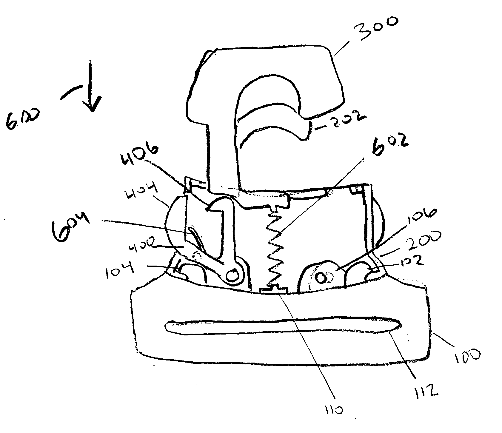
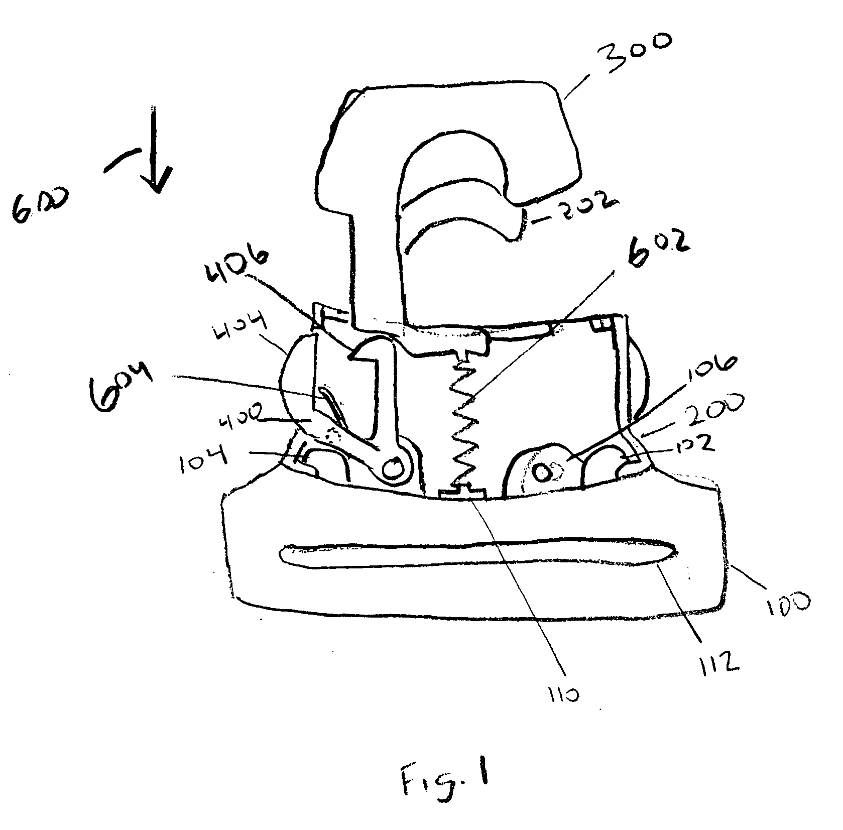
[0020]FIG. 1 depicts a first exemplary embodiment according to the present invention. The retaining assembly includes a first portion 100 and a second portion 200. The retaining assembly further includes a latching member 300. FIG. 1 depicts the latching member in an “open” position.

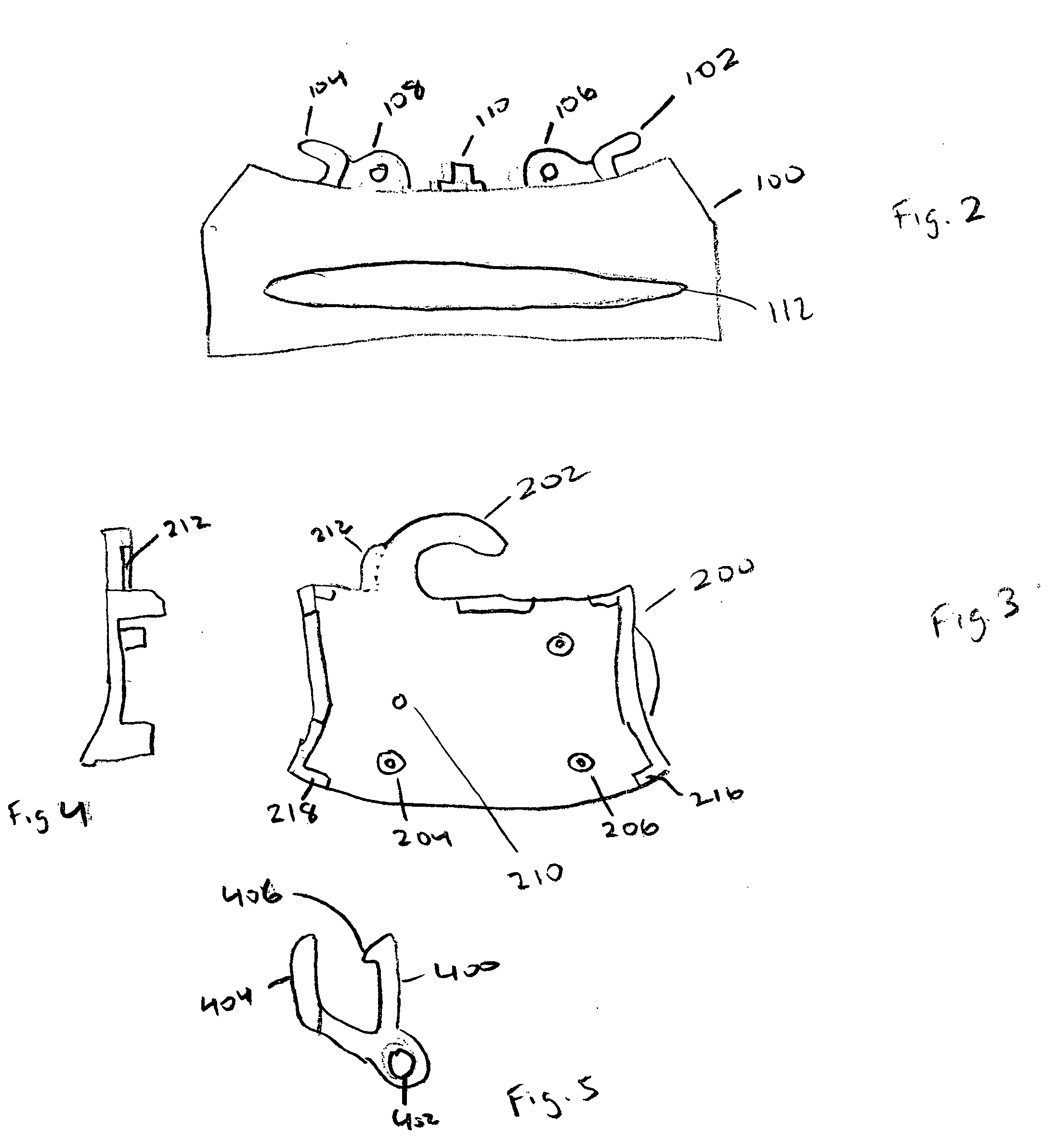
[0021]FIG. 2 depicts an isolated view of the first portion 100. The first portion 100 may be fabricated from a thermoplastic material or from a metal such as aluminum. The first portion 100 may include engaging features 102, 104. The first portion 100 may include boss retainers 106, 108. The first portion 100 may include a spring locator 110, for positioning a spring to cooperate with the latching member 300. The first portion 100 may also include a retaining slot 112 for attachment to a strap.

[0022]FIG. 3 depicts a front view of the second portion 200. The second portion 200 may be fabricated from a metal such as aluminum. The second portion 200 includes a retaining portion 202. The retaining portion ...


PUM


Abstract

A retaining assembly includes a first portion capable of being attached a strap, a second portion capable of being secured to the first portion, the second portion including a retaining portion capable of cooperating with a harnessing post; and a member capable of sliding over the retaining portion and cooperating with the second portion in a plurality of positions. When the member is in a first position, the combination of the retaining portion and the member is capable of retaining the harnessing post.

Description

FIELD [0001] This application relates generally to retaining assemblies and particularly to retaining assemblies for attaching a strap to an item of luggage. BACKGROUND INFORMATION [0002] Retaining assemblies serve a variety of functions. They can be used for attaching a set of keys to a belt buckle, for example, or may be used to hold a device such as a whistle, or may be used to attach a strap to an item of luggage. Many retaining assemblies include a generally J-shaped portion, and an additional portion to complete the “circle.” The additional portion typically communicates with a spring that keeps the additional portion pressed against the end of the J-shaped portion, unless a force is applied on a protrusion attached to the additional portion to overcome the spring force. In order to keep the additional portion in contact with the end of the J-shaped portion, a relatively stiff spring is chosen. Thus, depending on the application, the amount of force to be applied to the protru...

Claims


Application Information

Patent Timeline
IPC IPC(8): A43C11/00
CPCA45C13/1092Y10T24/4566Y10T24/45733
Inventor FENTON, TIMM JOHNSCICLUNA, PAUL VICTOR
Owner TUMI INC
Why Eureka
Try Eureka