Nail gun

Inactive Publication Date: 2006-07-06
APLUS PNEUMATIC CORP
View PDF5 Cites 7 Cited by
  • Summary
  • Abstract
  • Description
  • Claims
  • Application Information

AI Technical Summary

Benefits of technology

[0007] The primary advantage of the according to the present invention is its simplicity both in structure and operation compared with the conventional nail gun discussed in the Related Prior Art.

Problems solved by technology

The operation of this conventional nail gun is not reliable for the use of the pressing elements 17 and 18.

Method used


Image

  • Nail gun
  • Nail gun
  • Nail gun

Examples


Embodiment Construction

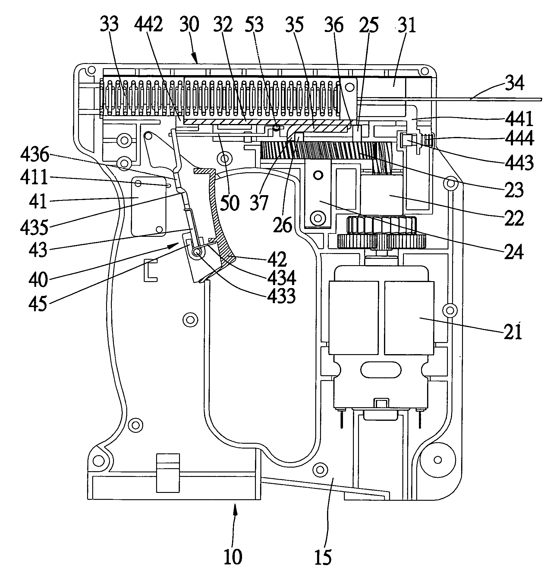
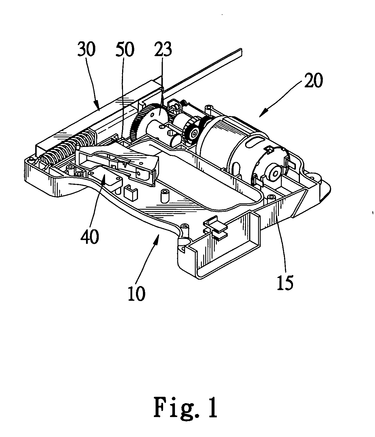
[0023] Referring to FIG. 1, a nail gun 10 includes a shell 15, a hammering device 30 for hammering nails, an energizing device 20 for providing energy to the hammering device 30, an actuating device 40 for actuating the energizing device 20 and a lever 50 for disabling the actuating device 40 after a nail is fired. The actuating device 50 can be reset in order to allow the firing of one more nail.

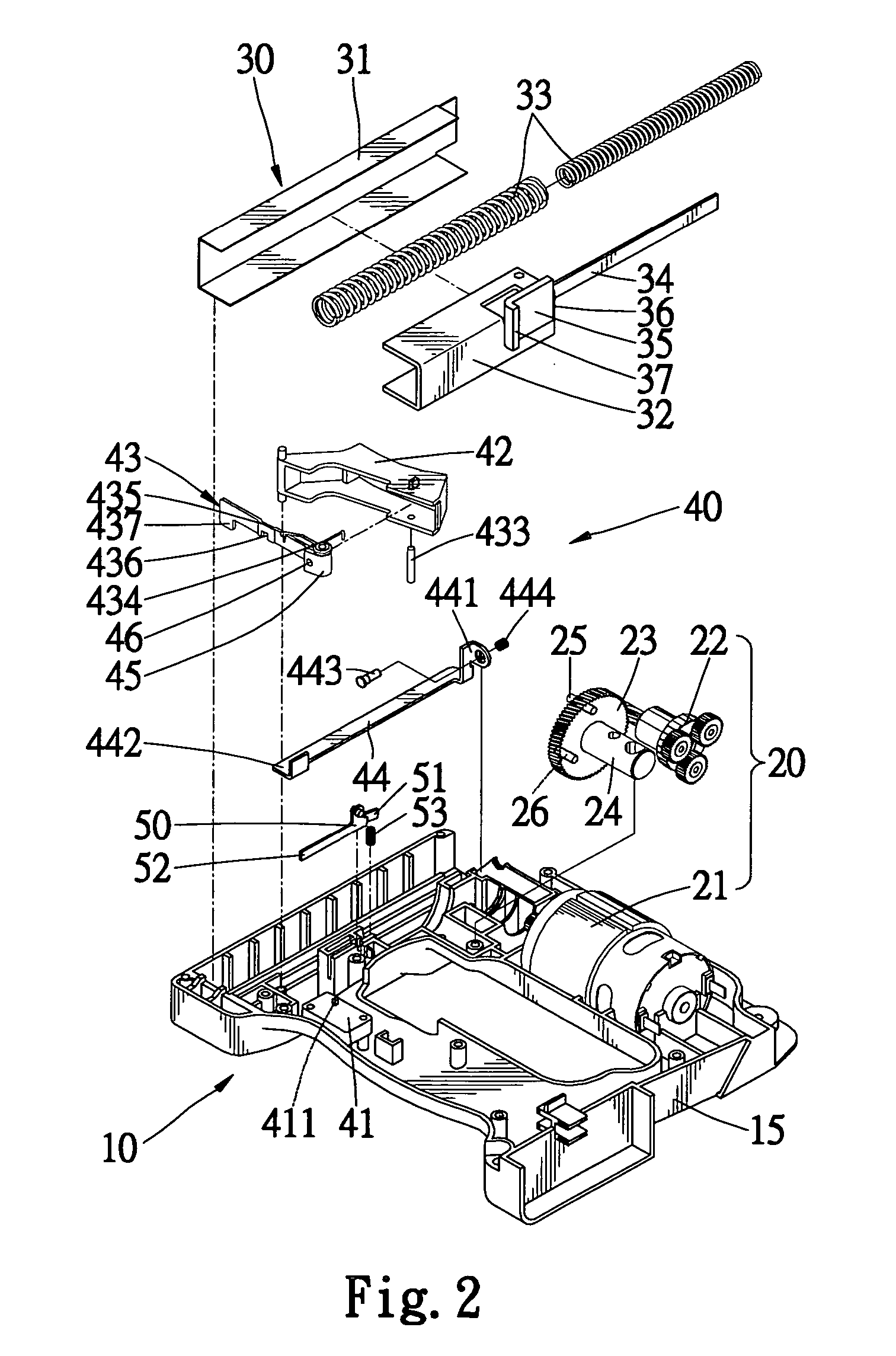
[0024] Referring to FIGS. 2 and 3, the energizing device 20 includes a motor 21 installed in the shell 15, a transmission 22 connected with the motor 21, a gear 23 connected with the transmission 22, and a shaft 24 for installing the gear 23 rotationally in the shell 15. A short rod 26 and a long rod 25 extend from a side of the gear 23.

[0025] The hammering device 30 includes a trough 31 installed in the shell 15, a hammer 32 movable in the trough 31, a pusher 34 secured to the hammer 32 and two springs 33 compressed between a portion of the shell 15 and a portion of the hammer 32. A tab ...


PUM

PropertyMeasurementUnit
Energyaaaaaaaaaa
Compressibilityaaaaaaaaaa

Abstract

A nail gun includes a shell, a hammering device for firing nails, an energizing device for providing energy to the hammering device, an actuating device for actuating the energizing device and a lever for disabling the actuating device after a nail is fired. The actuating device can be reset in order to allow the firing of one more nail.

Description

BACKGROUND OF INVENTION [0001] 1. Field of Invention [0002] The present invention relates to a nail gun that after firing a nail, does not fire another nail until it is disengaged from and engaged again with a work-piece. [0003] 2. Background of Invention [0004] According to U.S. Pat. No. 5,004,140, a conventional nail gun includes a switch 14, a trigger 16, a long pressing element 17, a short pressing element 18, a disc 10, a short pin 11, a long pin 12, a control member 19 and a lever 20. The structure and operation of this conventional nail gun are complicated for the use of two pressing elements 17 and 18. The operation of this conventional nail gun is not reliable for the use of the pressing elements 17 and 18. [0005] The present invention is therefore intended to obviate or at least alleviate the problems encountered in prior art. SUMMARY OF INVENTION [0006] According to the present invention, a nail gun includes a shell, a hammering device for firing nails, an energizing devi...

Claims


Application Information

Patent Timeline
IPC IPC(8): B25C5/02
CPCB25C1/06
Inventor CHEN, MU-YU
Owner APLUS PNEUMATIC CORP
Why Eureka
Try Eureka