Method and apparatus for producing non-planar formed parts using compaction molding compounds, and parts formed using same

a technology of compaction molding compound and formed parts, which is applied in the direction of dough shaping, manufacturing tools, food shaping, etc., can solve the problems of unintended variation of part density, part failure, mold failure, etc., and achieves high quality, high strength parts, efficient forming and high quality

Inactive Publication Date: 2005-05-03
SOH SUNG KUK
View PDF33 Cites 4 Cited by
  • Summary
  • Abstract
  • Description
  • Claims
  • Application Information

AI Technical Summary

Benefits of technology

[0021]It is an object of the present invention to provide a method and apparatus for efficiently forming high quality, high strength parts using CMC, wherein the formed parts are non-planar with relatively complex geometries deviating substantially from flat panels.
[0022]It is a further object of the present invention to provide such a method and apparatus which are relatively simple in structure and operation.
[0023]It is another object of the present invention to provide such a method and apparatus which are relatively low in cost.

Problems solved by technology

However, the part will fail if any portion of the part is compressed beyond the compressive strength limit of the CMC.
If any portion of the furnish reaches such a limit during the compacting cycle, the mold can not be closed further without destroying the part and / or the mold.
Even if the part does not fail, uneven compaction will often result in unacceptable and unintended variation of part density.
On the other hand, if any portion of the part is subject to draw or stretching deformation, failure by void formation or tear will be observed.
Due to the above-discussed considerations and restrictions on operating conditions, successful molding of CMCs has been limited to very simple part geometry which only requires very small deformation from flat sheet geometry of the preformed mat or initial furnish.
Otherwise, the mat easily tears apart during compaction if the mat is pulled by the draw.
Even if it does not tear, the draw decreases the density or forms voids, counteracting the desirable effect of compaction.
These patents report such difficulty in producing structurally sound drawn legs that they had to invent many additional steps to form the legs, such as interrupting the molding process to add more furnish in the drawn area or forming the drawn area in a separate molding step before the planar section is over-molded.
Such a technique, while it may be useful for certain cases, forces loss of design flexibility as the design is dictated and limitations put on it by the requirement of trying to counteract the effect of draw that creates density variation or void formation.
With the conventional practices described above, which use a simple two-platen press, some curved surfaces may be formed in one step from flat preformed mats or furnish, but the geometry of parts that can be formed thereby is very limited and the produced part has to be thinner in the drawn portion thereof.
Molding parts with multiple thicknesses with uniform density and structural integrity is not possible with this conventional technology.
Applicability of the technology disclosed in these patents is limited to formation of elongated structural beams, and the forming operation is limited to the specific sequence and magnitude of platen movements described.
As will be understood from the foregoing, although various CMCs and apparatus and methods for processing same are known, the conventional apparatus and methods have significant limitations and restrictions associated therewith.

Method used


Image

  • Method and apparatus for producing non-planar formed parts using compaction molding compounds, and parts formed using same
  • Method and apparatus for producing non-planar formed parts using compaction molding compounds, and parts formed using same
  • Method and apparatus for producing non-planar formed parts using compaction molding compounds, and parts formed using same

Examples


Embodiment Construction

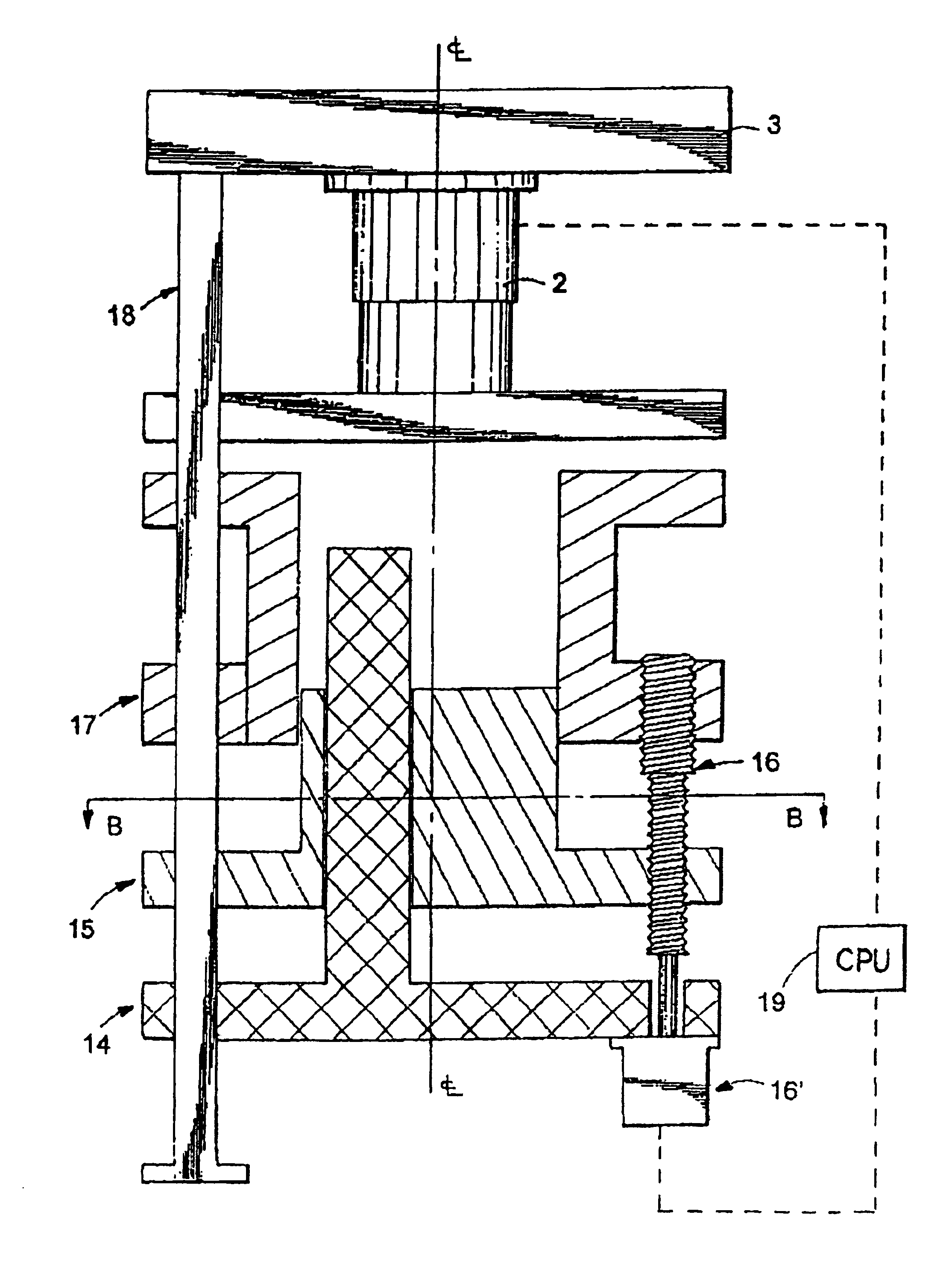
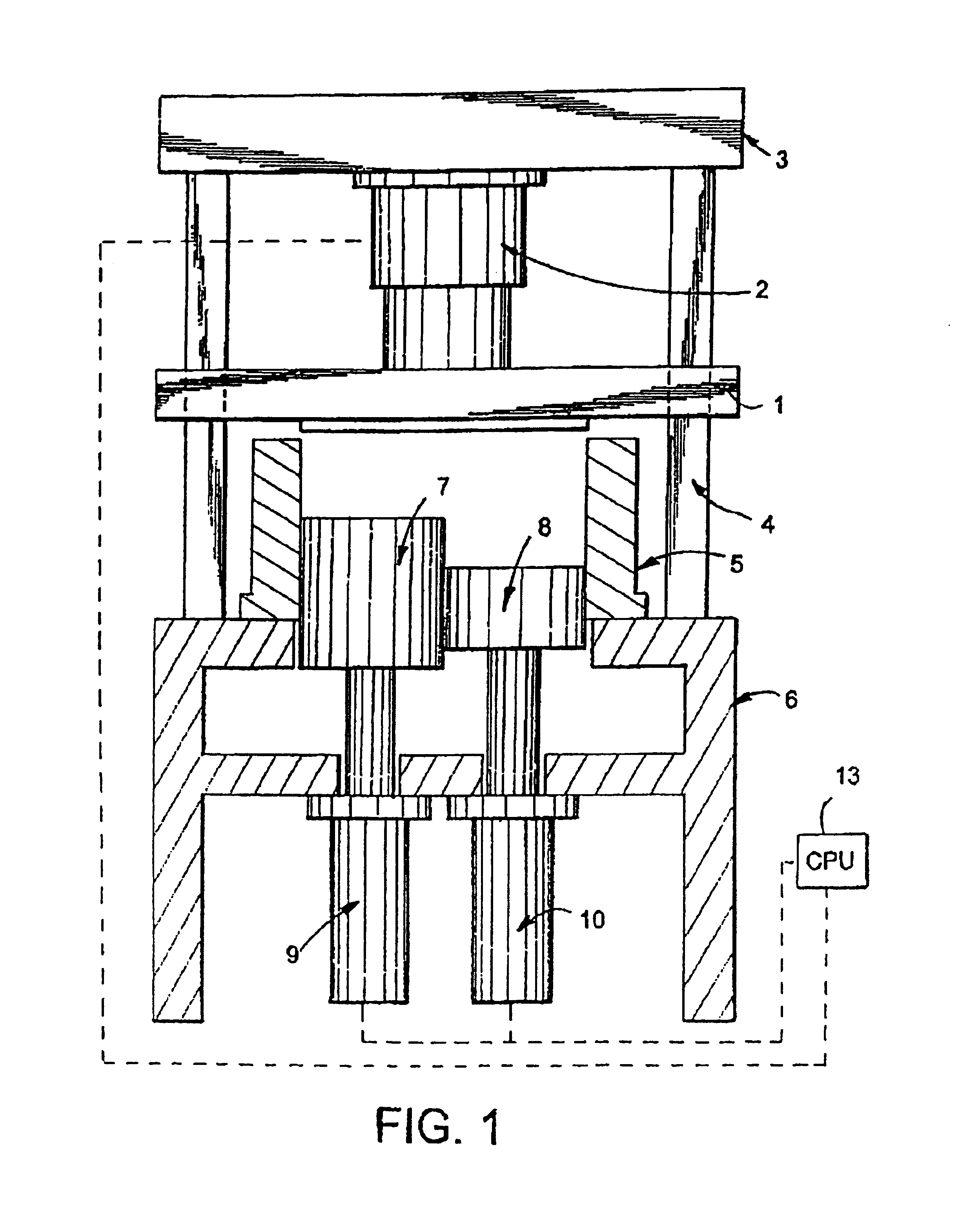
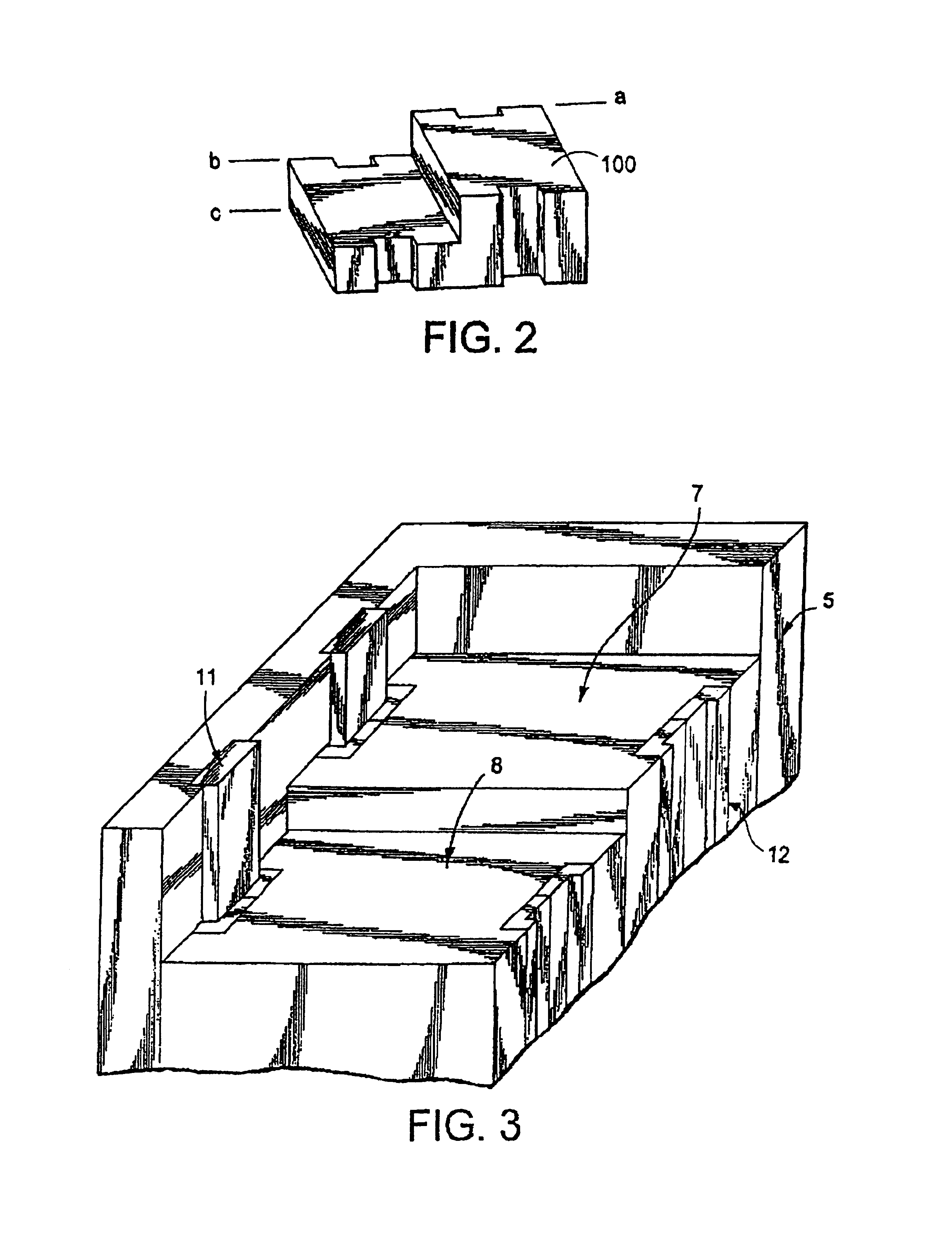
[0039]The present invention teaches the construction of various apparatus and methods of molding parts of complex shapes with compaction molding materials (or CMC). Description is presented below of several different embodiments of molding apparatus according to the invention. Prior to describing specific apparatus, however, a discussion is presented of method or processing conditions which are met by all of the different molding apparatus in forming non-planar parts according to the invention.

[0040]Molding Methods of the Invention

[0041]In order to produce desired part shapes while maintaining integrity and uniformity of material properties of the CMC, it is important to understand what conditions are preferably met during the molding of such material. The various apparatus and methods of the present invention recreate and maintain such conditions. Particularly, the inventor discovered that when the six conditions listed below are met during a molding cycle, geometrically complex no...


PUM

PropertyMeasurementUnit
velocitiesaaaaaaaaaa
densityaaaaaaaaaa
velocity ratioaaaaaaaaaa

Abstract

Molding apparatus for producing non-planar parts using compaction molding compounds (CMC) comprises a mold having a cavity which receives CMC therein, the mold including a movable platen assembly having at least two plates movable in substantially parallel directions to compact CMC placed in the cavity, and an actuating mechanism which moves the plates simultaneously at different respective velocities such that the CMC is substantially uniformly compacted into a non-planar shape with a predetermined, substantially uniform density.

Description

BACKGROUND OF THE INVENTION[0001]1. Field of the Invention[0002]The present invention relates to an improved method and apparatus for producing formed or molded parts from molding materials that do not flow freely, which will be referred to as compaction molding compounds. More particularly, the present invention pertains to such a method and apparatus which can be efficiently used to mold high quality shaped or non-planar parts from inexpensive compaction molding compounds.[0003]2. Description of the Background Art[0004]In the art, compaction molding compounds (or CMC), as well as apparatus (molds, presses, etc.) and methods used to compact such materials into boards and other planar or nearly planar objects, are known.[0005]Compaction molding materials have been commonly prepared by mixing suitable solid material such as wood chips, fiber, grain hulls, straw, sawdust, papermill sludge (see, for example U.S. Pat. No. 4,303,019), etc. or mixtures thereof with a suitable binder or bi...

Claims


Application Information

Patent Timeline
Patent Type & Authority Patents(United States)
IPC IPC(8): B29C43/58B29C43/00B27N5/00B27N3/08
CPCB27N3/08B27N5/00B29C43/003B29C43/58B29K2311/14B29C2043/3615B29C2043/5808B29C2043/5833
Inventor SOH, SUNG KUK
Owner SOH SUNG KUK
Why Eureka
Try Eureka