Platinum-Coated Non-Noble Metal-Noble Metal Core-Shell Electrocatalysts

a core-shell electrocatalyst, non-noble metal technology, applied in the direction of metal/metal-oxide/metal-hydroxide catalysts, physical/chemical process catalysts, cell components, etc., can solve the problem of affecting the successful implementation of fuel cells in commercially available fuel cells, affecting the surface area available for reaction, and affecting the efficiency of forming

Inactive Publication Date: 2010-08-05
BROOKHAVEN SCI ASSOCS
View PDF2 Cites 85 Cited by
  • Summary
  • Abstract
  • Description
  • Claims
  • Application Information

AI Technical Summary

Benefits of technology

[0011]In view of the above-described problems, needs, and goals, some embodiments of the present invention provide electrocatalyst supports with minimal loading of noble metals and a concomitant enhancement in catalytic activity. Another aspect of the present invention is to provide a method of efficiently forming said electrocatalyst supports. In one embodiment this is accomplished by forming core-shell particles in which a non-noble metal core is surrounded by a shell of a noble metal. The use of a non-noble metal as the primary bulk constituent minimizes loading of more costly noble metals whereas the noble metal shell protects the underlying core from dissolution during exposure to corrosive environments. The core-shell particle is preferably at least partially encapsulated by a thin film of a catalytically active material which provides active surface sites for reaction.
[0012]The core-shell particle preferably has external dimensions ranging from 1-100 nm and is thus a nanoparticle. In a preferred embodiment, the external dimensions of the core-shell nanoparticles are between a minimum of 2 nm and a maximum of 10 nm. The shape of the core-shell particle is preferably spherical, but is not so limited and may take on any shape as is well-known in the art. These include, but are not limited to, nanostructures which are spherical, pyramidal, rod-shaped, cubic, tubular, cuboctahedral, tetrahedral, wire-like, nanotube-like, and so forth. The catalytically active surface layer is preferably a contiguous thin film which encapsulates the core-shell nanoparticle with a surface coverage ranging from less than a monolayer to several monolayers. Such coated nanoparticles facilitate more efficient and cost-effective electrochemical energy conversion in fuel cells, metal-air batteries, and during corrosion processes.
[0014]The composition of the shell itself is preferably homogeneous, but may also be nonuniform. The noble metal shell is preferably comprised of at least one of palladium (Pd), iridium (Ir), rhenium (Re), or gold (Au). Thus, in this embodiment the electrocatalyst is preferably a non-noble metal-noble metal core-shell nanoparticle. In an even more preferred embodiment, the shell is a noble metal other than platinum (Pt). Considering the scarcity and high cost of Pt, producing a core and shell without this more precious metal provides additional cost savings. Furthermore, the presence of geometric and / or electronic effects between the underlying shell and the catalytically active overlayer may serve to actually increase the catalytic activity per unit mass of Pt used.

Problems solved by technology

A reduction to nanoscale dimensions yields a significant increase in the surface-to-volume ratio, producing a concomitant increase in the surface area available for reaction.
Pt has been shown to be one of the best electrocatalysts, but its successful implementation in commercially available fuel cells is hindered by its extremely high cost, susceptibility to carbon monoxide (CO) poisoning, poor stability under cyclic loading, and the relatively slow kinetics of O2 reduction at the cathode.
Attempts to accelerate the oxidation reduction reaction (ORR) on Pt while simultaneously reducing Pt loading have been met with limited success.

Method used


Image

  • Platinum-Coated Non-Noble Metal-Noble Metal Core-Shell Electrocatalysts
  • Platinum-Coated Non-Noble Metal-Noble Metal Core-Shell Electrocatalysts
  • Platinum-Coated Non-Noble Metal-Noble Metal Core-Shell Electrocatalysts

Examples


example 1

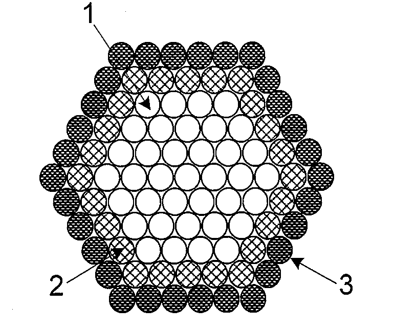
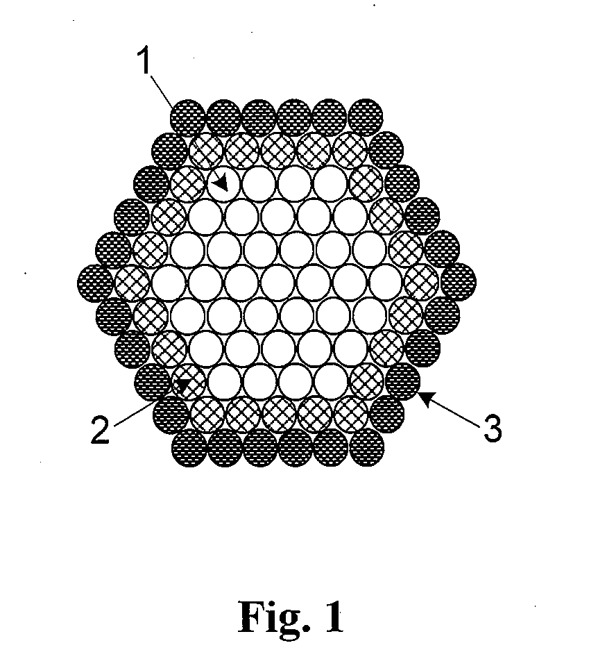
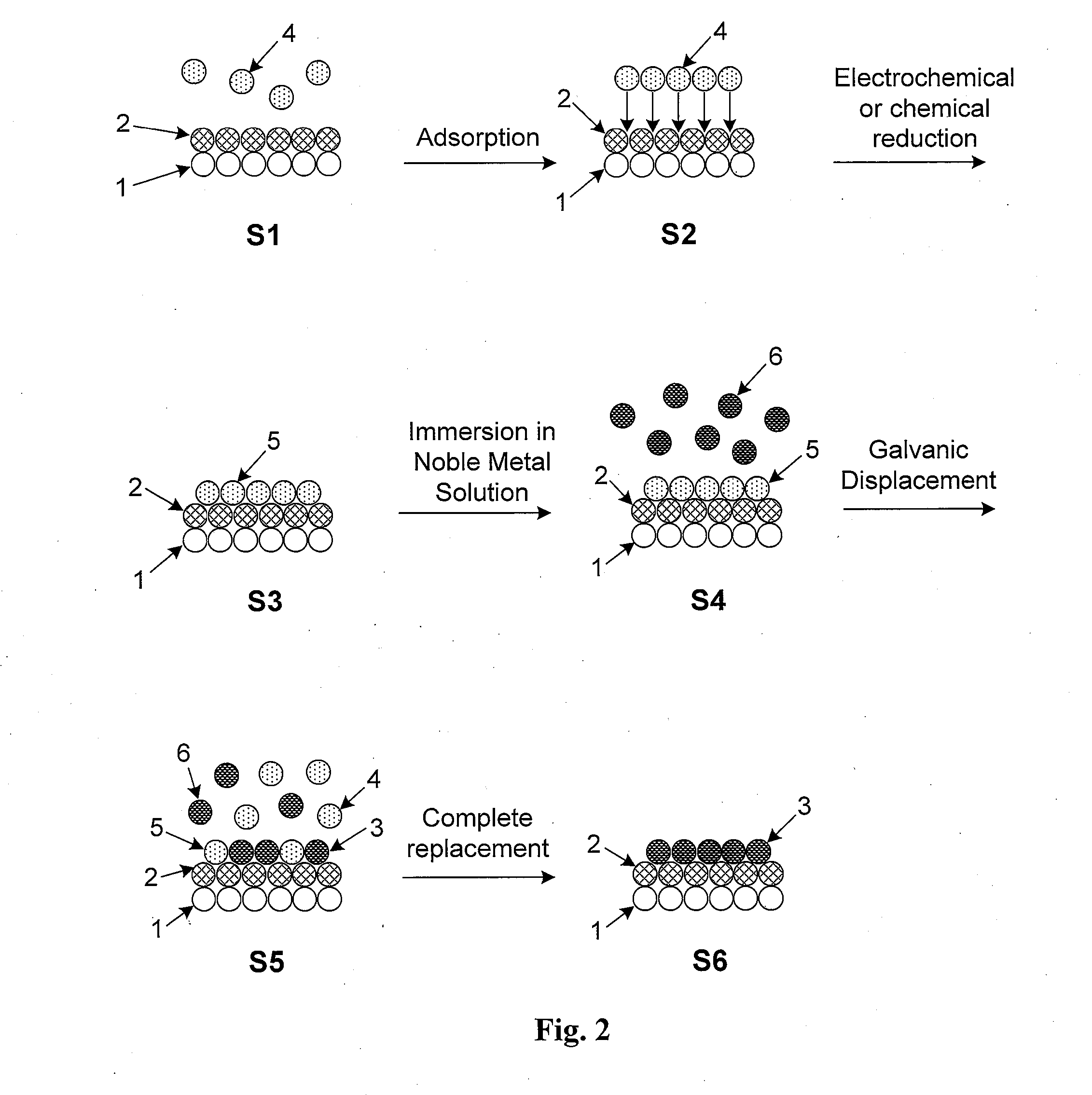
[0070]In one embodiment sodium boronhydride is used to reduce a room-temperature suspension comprising PdCl2 and CoCl2 salts mixed in a 1:1 to 1:10 ratio. The sample is dried and then held in an inert or reducing environment at 600° C. for one hour to drive surface segregation of Pd atoms. For purposes of this embodiment, only the first two surface atomic layers of a self-protecting nanoparticle alloy are shown in FIG. 2. The nanoparticle surface in FIG. 2 shows a portion of the non-noble metal core (1) along with the noble metal shell (2) which, in this embodiment, are Co and Pd, respectively.

[0071]Non-noble metal ions of Cu2+ (4) are initially adsorbed on the surface by immersing the nanoparticles in a plating bath comprising the appropriate concentration of Cu2+ ions (4) in step S1. UPD of Cu results in the adsorption of Cu2+ ions (4) on the nanoparticle surface in step S2 and the formation of a monolayer of Cu (5) in step S3. This monolayer forms a continuous Cu “skin” around th...

example 2

[0073]In another embodiment a nickel core encapsulated by an atomically thin layer of gold was prepared by treating an aqueous suspension containing one equivalent of gold chloride (AuCl3), ten equivalents of nickel chloride (NiCl2), and carbon powder, with sodium borohydride art room temperature. The water of the resulting suspension of reduced metal was removed, and the resulting powder dried under an inert atmosphere. In order to ensure gold segregation onto the nickel surface, the dried powder was then annealed under a pure hydrogen gas environment at 600° C. for one hour. A platinum monolayer was deposited onto the gold-nickel particles by redox displacement by platinum of an adlayer of an underpotentially deposited (UPD) metal. In this example, Cu was used as the UPD metal on the gold-nickel / carbon nanoparticle substrate.

[0074]To prepare an electrode with gold-nickel nanoparticles, a dispersion of carbon-supported gold-nickel nanoparticles (AuNi / C) on a carbon substrate was ma...


PUM

PropertyMeasurementUnit
temperatureaaaaaaaaaa

Abstract

Core-shell particles encapsulated by a thin film of a catalytically active metal are described. The particles are preferably nanoparticles comprising a non-noble core with a noble metal shell which preferably do not include Pt. The non-noble metal-noble metal core-shell nanoparticles are encapsulated by a catalytically active metal which is preferably Pt. The core-shell nanoparticles are preferably formed by prolonged elevated-temperature annealing of nanoparticle alloys in an inert environment. This causes the noble metal component to surface segregate and form an atomically thin shell. The Pt overlayer is formed by a process involving the underpotential deposition of a monolayer of a non-noble metal followed by immersion in a solution comprising a Pt salt. A thin Pt layer forms via the galvanic displacement of non-noble surface atoms by more noble Pt atoms in the salt. The overall process is a robust and cost-efficient method for forming Pt-coated non-noble metal-noble metal core-shell nanoparticles.

Description

[0001]This application claims priority under 35 U.S.C. §119(e) to U.S. Provisional Patent Application No. 61 / 153,424 which was filed on Feb. 18, 2009, and is a continuation-in-part of and claims priority under 35 U.S.C. §120 to co-pending U.S. patent application Ser. No. 11 / 156,038 which was filed on Jun. 20, 2005 and which, in turn, is a continuation-in-part of and claims priority under 35 U.S.C. §120 to co-pending U.S. patent application Ser. No. 11 / 019,759 which was filed on Dec. 22, 2004, the entirety of all of which are incorporated by reference as if fully set forth in this specification.[0002]This invention was made with Government support under contract number. DE-AC02-98CH10886, awarded by the U.S. Department of Energy. The Government has certain rights in the invention.BACKGROUND OF THE INVENTION[0003]I. Field of the Invention[0004]This invention relates generally to core-shell electrocatalyst supports. In particular, the present invention relates to core-shell electrocata...

Claims


Application Information

Patent Timeline
Patent Type & Authority Applications(United States)
IPC IPC(8): B01J23/42B01J23/89
CPCB01J23/44B01J35/0013B82Y30/00H01M4/8657Y02E60/50H01M4/926H01M4/928H01M2008/1095H01M4/921
Inventor ADZIC, RADOSLAVZHANG, JUNLIANGMO, YIBOVUKMIROVIC, MIOMIR
Owner BROOKHAVEN SCI ASSOCS
Why Eureka
Try Eureka