Filling valve

a filling valve and liquid technology, applied in liquid handling, packaging goods, transportation and packaging, etc., can solve the problems of deformation of the vessel, complicated structure, and failure to achieve seals, and achieves simple structure, reduced wall thickness, and small aperture

Active Publication Date: 2007-10-30
SHIBUYA IND CO LTD
View PDF4 Cites 15 Cited by
  • Summary
  • Abstract
  • Description
  • Claims
  • Application Information

AI Technical Summary

Benefits of technology

[0010]Accordingly, it is an object of the present invention to provide a filling valve capable of a combined use with vessels of different aperture diameters while retaining a simple structure.
[0012]The filling valve according to the present invention has a simple structure while allowing a filling operation to be performed with a required minimum load on the mouth and barrel of the bottle-like first type vessel having a smaller aperture diameter and the second type vessel having a larger aperture diameter, such as a canister, and thus can be selectively used with an aluminum canister of a reduced wall thickness and an aluminum bottom or the like.

Problems solved by technology

In the arrangement of the cited patent, when the second type vessel of a larger aperture, such as a canister, is to be filled, in particular, when a canister having a reduced wall thickness is to be filled, it is to be noted that there arises a problem that an imbalance between a force applied from a filling valve and a force from the vessel prevents a seal from being successfully achieved because the aperture of the canister which is sealed by the gasket associated with the canister is greatly different from the aperture of the filling valve.
In addition, if the gasket is forcibly urged against the vessel in order to achieve a reliable seal, there occurs a deformation of the vessel.
In addition, the gas passage 152 needs to be cleaned, resulting in complicating the structure.

Method used


Image

  • Filling valve
  • Filling valve
  • Filling valve

Examples


Embodiment Construction

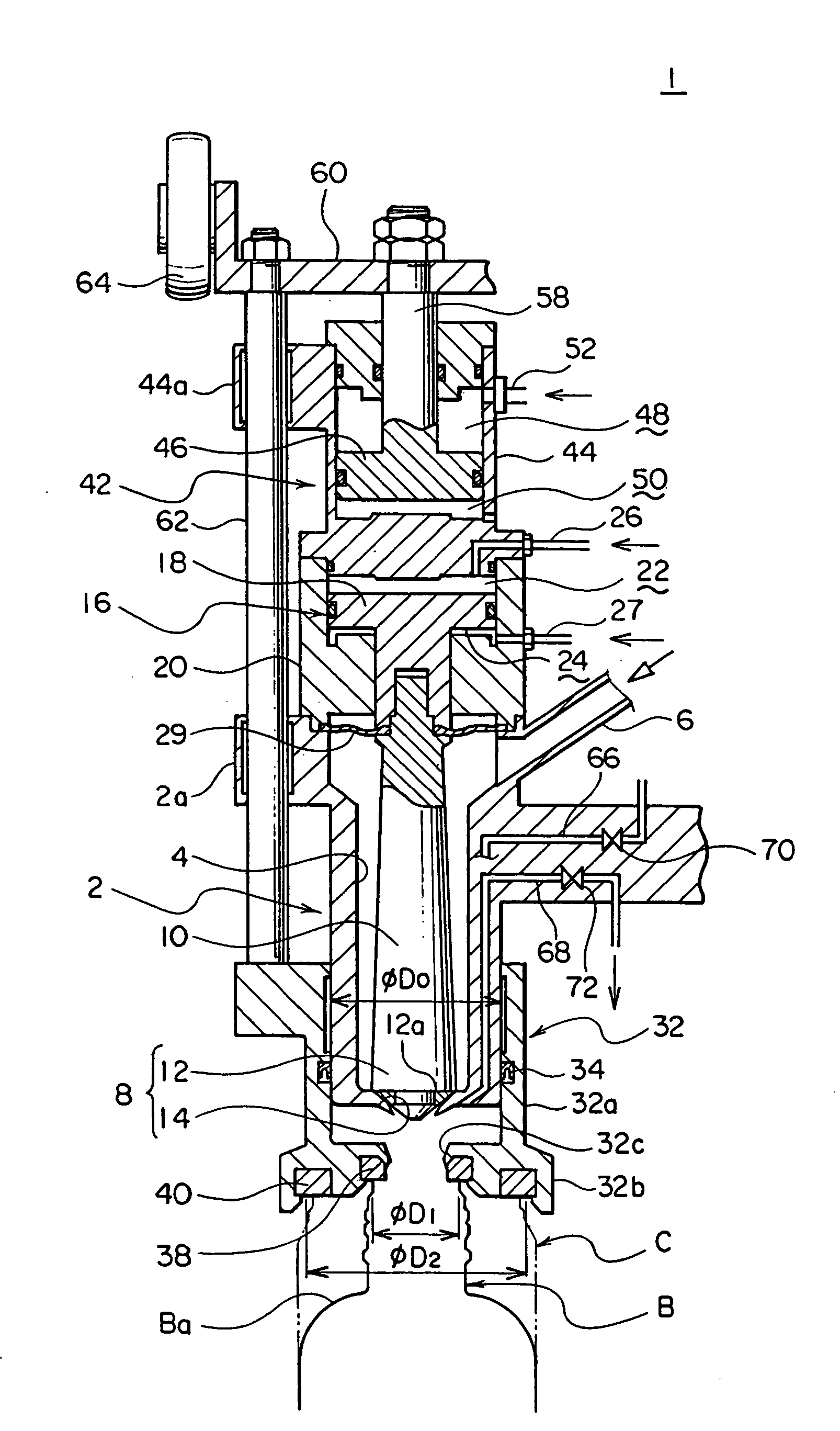
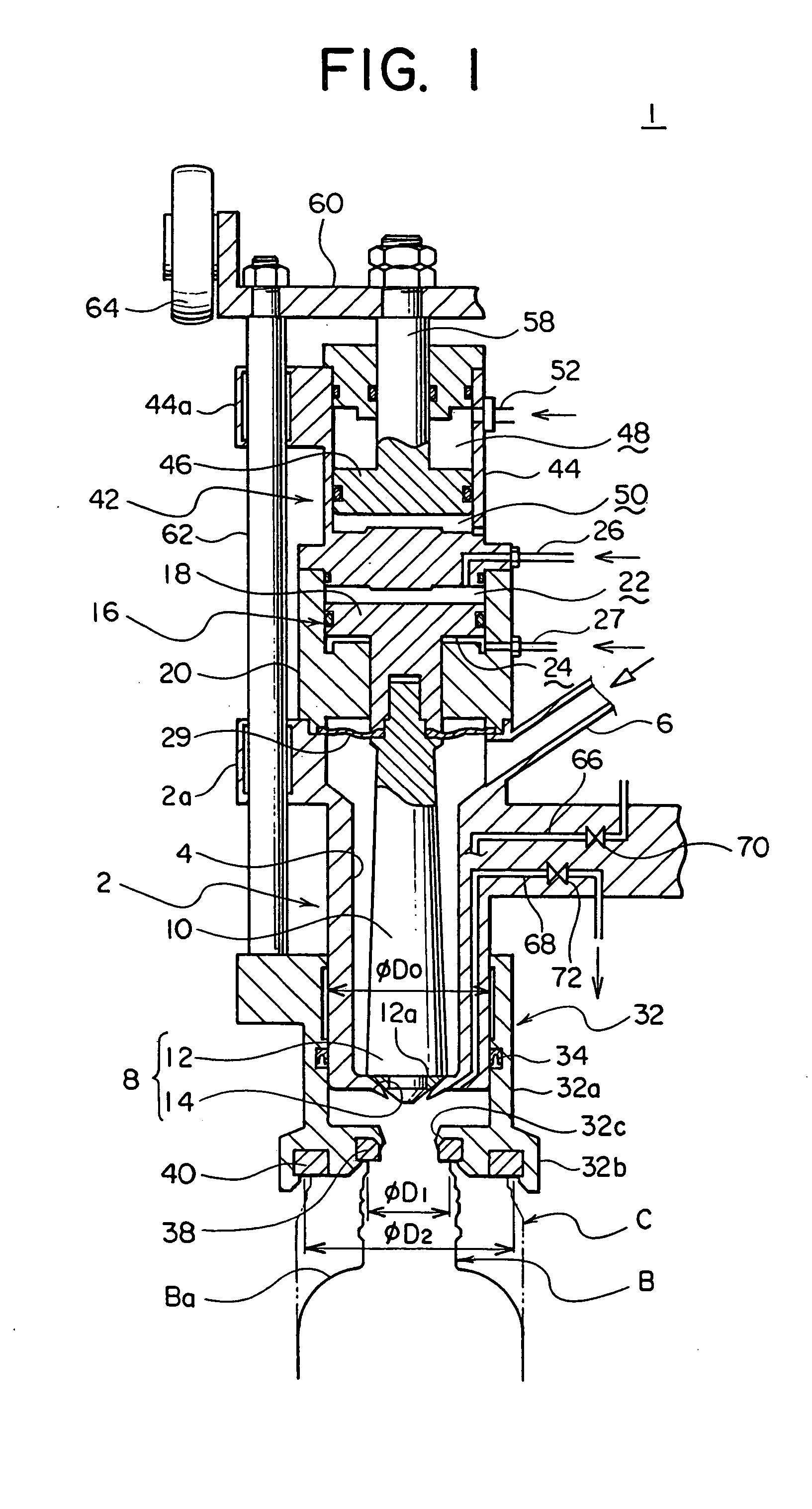
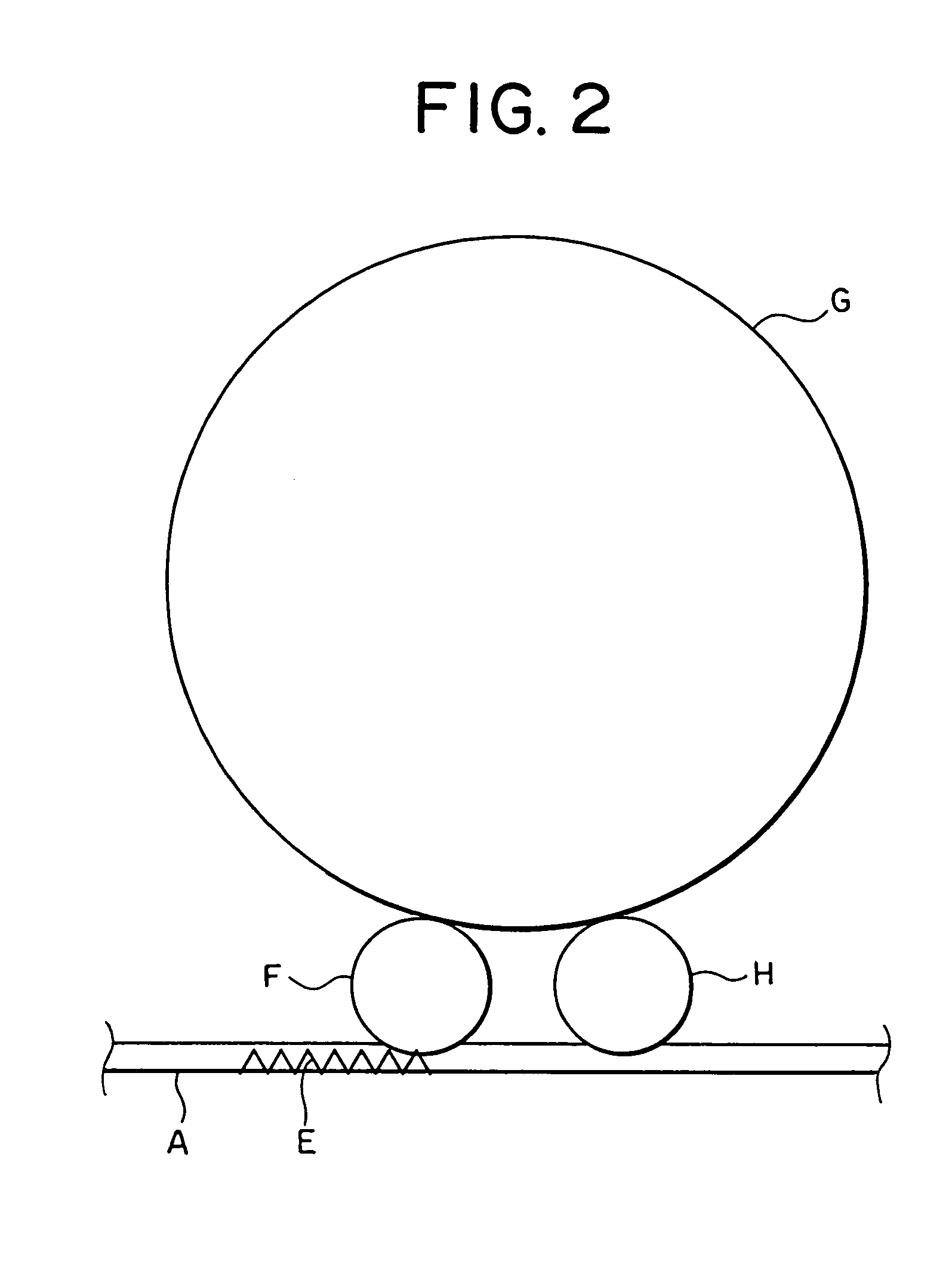
[0017]An embodiment of the present invention will now be described with reference to the drawings. Referring to FIG. 2, vessels B or C which are conveyed by a vessel conveyor A (FIG. 1 indicates two type of vessels concurrently) are separated into a given interval by an in-feed screw E, and delivered onto a rotary filler G through an inlet star wheel F. A liquid is filled into each vessel B or C by the filling valve 1 during the time it is rotatively conveyed by the filler G, and it is then discharged onto the vessel conveyor A by an outlet star wheel H to be fed to a succeeding step.

[0018]It is to be understood that the rotary filler G includes a revolving body and a plurality of filling valves 1 are disposed at a given circumferential interval along the outer periphery thereof. One of the filling valves 1 is disposed in vertical alignment with one of the vessels B or C which are located therebelow, and a filling operation takes place while both filling valves and the vessels rotat...


PUM

PropertyMeasurementUnit
aperture diameteraaaaaaaaaa
outer diameteraaaaaaaaaa
diameteraaaaaaaaaa

Abstract

A vessel mouth gasket unit is fitted around the outer periphery of a valve body which is internally formed with a filled liquid passage. A first gasket having a smaller diameter and a second gasket having a larger diameter is mounted on the lower surface of the unit. The filling valve is made up of a liquid valve opening and closing air cylinder which opens and closes a liquid valve 8 disposed in the filled liquid passage, and a vessel mouth gasket auxiliary air cylinder which urges the unit downward. The valve body has an outer diameter which is greater than the aperture diameter of a bottle-like first type vessel and less than the aperture diameter of a second type vessel having a larger aperture. The operating pressure of the auxiliary air cylinder is controllable and the filling operation takes place by urging the gasket against the first vessel with a low load and by urging the gasket against the second type vessel with a high load. The filling valve enables a combined use for filling the bottle-like first type vessel B and the second type vessel without requiring a replacement of parts.

Description

BACKGROUND OF THE INVENTION AND RELATED ART STATEMENT[0001]The present invention relates to a liquid filling valve which is used to fill a liquid into a vessel while the interior of the vessel is sealed, and in particular, to a filling valve employed in a filler which can be selectively used with a bottle-like vessel of a smaller mouth aperture (referred to hereafter as a first type vessel) such as a vessel or bottle which-can be resealed with a cap as exemplified by a PET bottle and also with a vessel having a larger aperture such as a canister (hereinafter referred to as a second type vessel).[0002]Generally a filler is provided with a filling valve which comprises a filled liquid passage formed within a valve body, and a liquid valve which opens or closes the filled liquid passage. By opening the liquid valve, the liquid to be filled is injected into the vessel through the filled liquid passage. When the filler is used to fill a carbonic acid gas-charged beverage into a vessel, i...

Claims


Application Information

Patent Timeline
Patent Type & Authority Patents(United States)
IPC IPC(8): B65B1/04B67C3/26
CPCB67C3/2614B67C2003/2668B67C2003/2657
Inventor TANIKAWA, KATSUNORIKAMORI, SHINYAKONISHI, FUTOSHITSUKANO, KENICHI
Owner SHIBUYA IND CO LTD
Why Eureka
Try Eureka