Method for Producing an Electricity Sensing Device

a technology of sensing device and electricity, which is applied in the manufacture of coils, instruments, inductances, etc., can solve the problems of only being able to check the joint for absolute assurance, adding to the complications of assembling the primary busbar, and highly restricted possibility of checking the proper jointing. , to achieve the effect of simple fabrication, safe connection and minimum load

Inactive Publication Date: 2010-04-15
VACUUMSCHMELZE GMBH & CO KG
View PDF16 Cites 14 Cited by
  • Summary
  • Abstract
  • Description
  • Claims
  • Application Information

AI Technical Summary

Benefits of technology

[0012]Disclosed herein is a method for producing an electricity sensing device which assures simple fabrication for a safer connection with minimum load on the other components.

Problems solved by technology

Although it is possible to adapt the inner diameter of the inductive current transformer to the minimum possible by the electromagnetic design, when the primary conductor comprises a plurality of separate parts, this adds to the complications in assembling the primary busbar.
Both of these methods make it necessary to protect the current transformer from the heat generated in jointing, this in turn necessitating complicated designs with cooling clamps between the jointing location and current transformer.
Another drawback of these methods is the highly restricted possibility of checking proper jointing.
Indeed, checking the joint for absolute assurance is only possible by destructive testing.
In addition to this, there is a risk of electrochemical corrosion of the joint due to the difference in the normal potentials of the alloys used, as is especially the case with brazed connections depending on the combination of solder and conductor material employed.
Although this method avoids the heating-up of the joint, the resulting joints of the separate components of the primary conductor have other disadvantages.
The majority of the connecting surface is merely positively connected, resulting in a micron air gap remaining between the partners of the joint.
This air gap reduces the current-carrying capacity of the joint, resulting in the risk of the joint becoming over-heated when the conductor is loaded to a maximum.
For good electrical conductivity the corresponding busbars or conductor assemblies are mainly structured in a copper material, causing problems, however, both with brazing and welding, particularly due to the heat in making the joints, because copper is a good thermal conductor, so that the heat is transmitted by the current conductor to the current transformer, risking damage thereto.

Method used


Image

  • Method for Producing an Electricity Sensing Device
  • Method for Producing an Electricity Sensing Device
  • Method for Producing an Electricity Sensing Device

Examples


Embodiment Construction

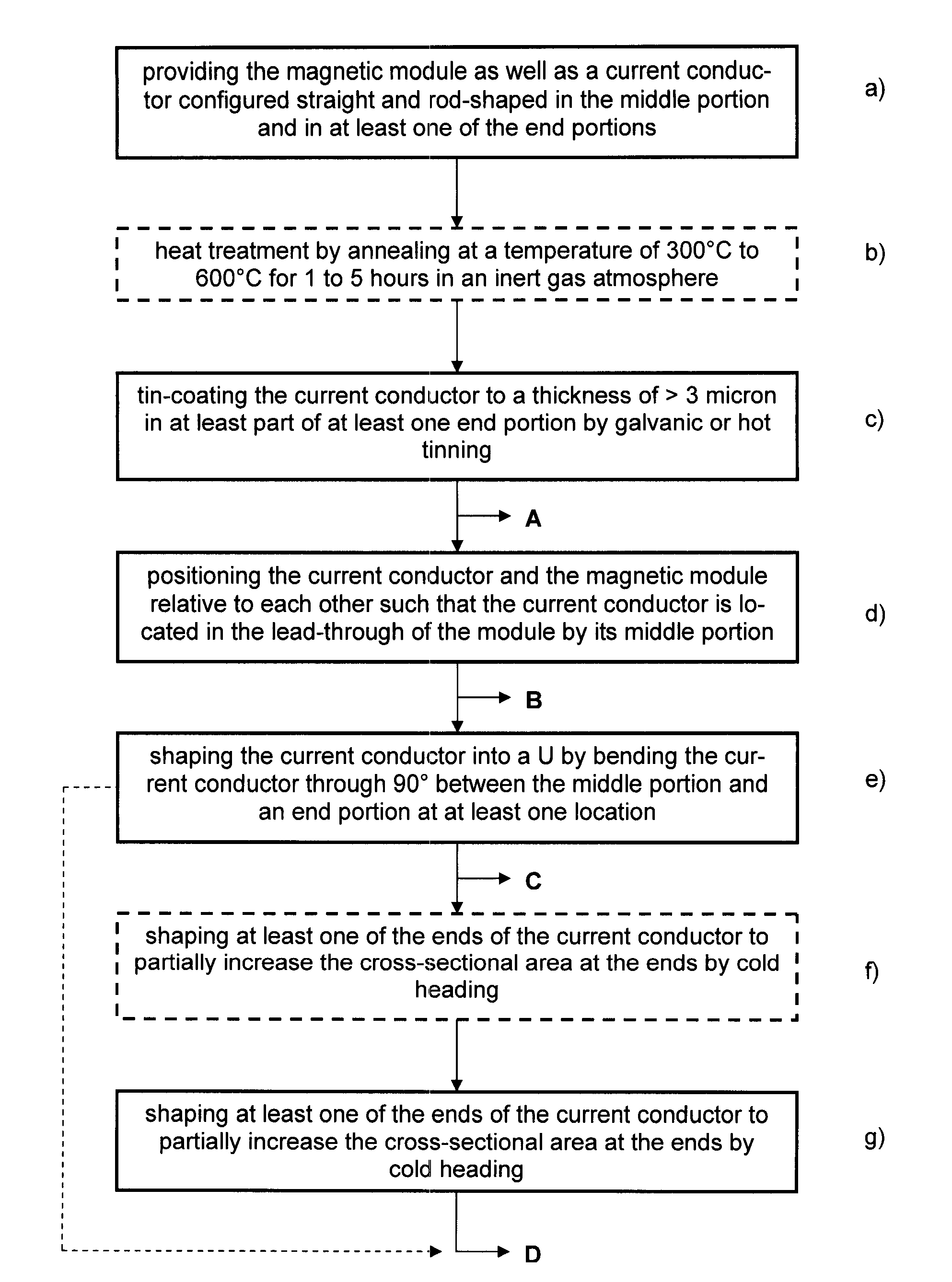
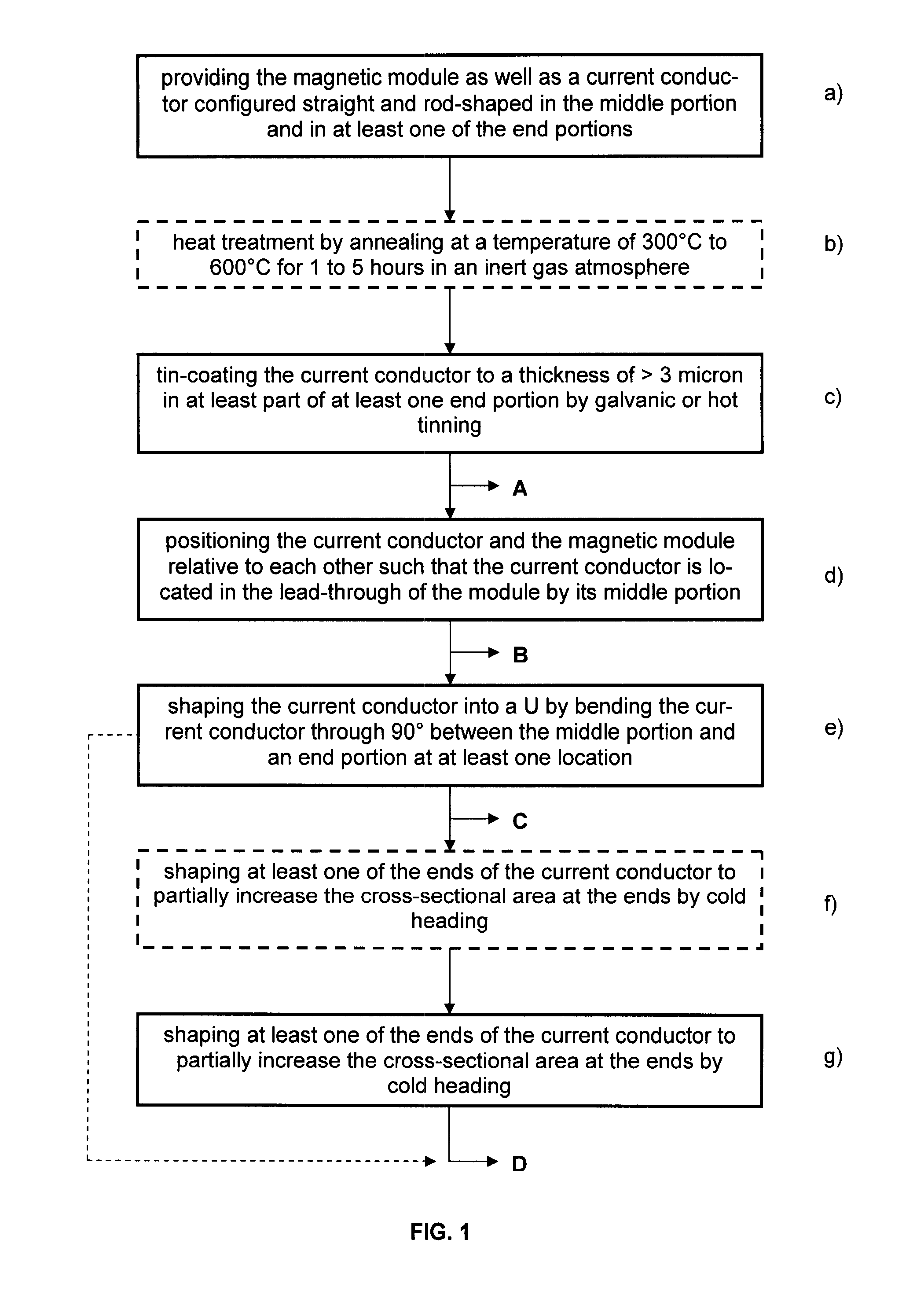
[0023]Referring now to FIG. 1 a flow diagram of the novel method of production is illustrated as an example, the end product of which is, for example, a current transformer, a current sensor or the like.

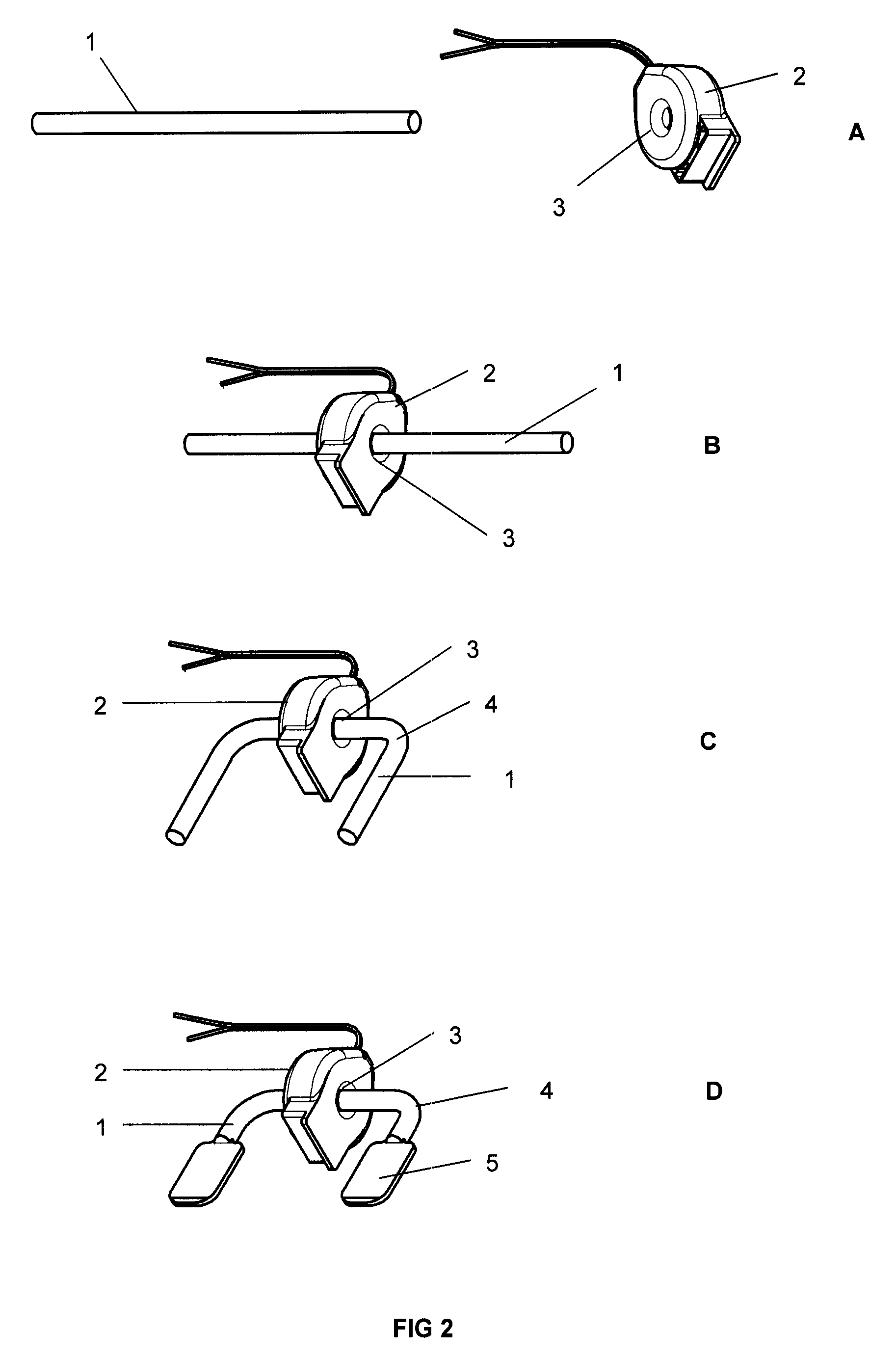
[0024]FIG. 2 illustrates one such end product denoted “D”. This electricity sensing device comprises, as shown, a one-piece U-shaped bent current conductor 1 of a certain length having a middle portion and two end portions and comprising in the middle portion the form of a rod having a non-rectangular conductor cross-section and featuring flats 5 having a rectangular conductor cross-section in its end portion. Provided furthermore is a magnetic module 2 arranged in the middle portion of the current conductor 1 (also termed primary conductor in accordance with its function) comprising a lead-through 3 receiving the current conductor. Such a module may include, as shown, at least one wound ring core and, depending on the circumstances, also an electronic circuit, such as, for instance,...


PUM

PropertyMeasurementUnit
temperaturesaaaaaaaaaa
thickaaaaaaaaaa

Abstract

A method for producing an electricity sensing device with a one-piece, U-shaped bent current conductor of a certain length having a middle portion and two end portions and comprising in the middle portion the form of a rod having a non-rectangular conductor cross-section and featuring flats having a rectangular conductor cross-section in its end portions, and arranged in the middle portion a magnetic module comprising a lead-through for mounting the current conductor, the method comprising the steps: providing the magnetic module as well as a current conductor configured straight and rod-shaped in the middle portion and in at least one of the end portions; tin-coating the current conductor at least partly in at least one end portion; positioning the current conductor and the magnetic module relative to each other such that the current conductor is located in the lead-through of the module by its middle portion, and shaping the current conductor into a U with flattened ends.

Description

BACKGROUND[0001]1. Field[0002]Disclosed herein is a method for producing an electricity sensing device such as, for example, an electricity meter or energy meter.[0003]2. Description of Related Art[0004]A variety of electronic electricity meters (or electric meters in US parlance) is known for sensing electricity or energy which are now increasingly taking the place of the mechanical Ferraris meters in industry and domestic applications and which implement electricity sensing by mechanical and electrical assemblies in diverse configurations. In addition to electricity sensing by means of measuring shunts, Rogowski coils or Hall elements, current transformers based on soft magnetic ring cores, especially ring band cores, are popular as magnetic modules in electricity meters. A magnetic module (current transformer) DC decouples the power to furnish a precise measurand in the form of a signal voltage across a burden resistor. The requirements as to the accuracy of amplitude and phasing...

Claims


Application Information

Patent Timeline
Patent Type & Authority Applications(United States)
IPC IPC(8): G01R19/00H01R43/00
CPCH01F27/292H01F38/30Y10T29/49117H01F2038/305H01F41/10
Inventor BRUNNER, MARKUSKEHLENBACH, MARTIN
Owner VACUUMSCHMELZE GMBH & CO KG
Why Eureka
Try Eureka