Showerhead

Active Publication Date: 2006-07-13
TOTO LTD
View PDF6 Cites 25 Cited by
  • Summary
  • Abstract
  • Description
  • Claims
  • Application Information

AI Technical Summary

Benefits of technology

[0008] It is therefore an object of the present invention to provide a showerhead capable of suppressing water dripping after stop of water discharge.
[0028] Furthermore, the showerhead of the present invention makes it possible to discharge water in aesthetic streamlines even when a water pressure is low.

Problems solved by technology

However, it is difficult to dimensionally increase the aforementioned conventional showerhead without structural modification so as to obtain a practicable large-size showerhead having a convexedly-curved-shaped shower plate simply increased in diameter.
Specifically, if the conventional showerhead is simply increased in dimension, an area to be subjected to a water pressure will be inevitably increased in the inside of the showerhead.
This is likely to cause a problem about water leakage.
Further, the deformation in the components of the showerhead is likely to damage a connection between the showerhead body and the shower plate or a connection of the shower head and the pipe to cause a problem about dropping-off of the spray pipe or the showerhead
Moreover, if the conventional showerhead is simply increased in dimension, a void space in the showerhead will be inevitably increased, and a large volume of water will undesirably remain in the void space as residual water when the shower water is stopped.
That is, the surface tension becomes uneven at the respective splay holes.
In the result, the surface tension at some of the discharging holes becomes unable to withstand atmospheric pressure, and outside air flows into the showerhead through these discharging holes.
The inflow air presses the residual water in the showerhead to cause a problem about continuous water dripping from a part of the discharging holes.
Furthermore, if the showerhead formed with the discharging holes arranged, respectively, along a plurality of lines extending radially from the center of a sphere defined by the curved surface of the shower plate is attached at a position having a low water pressure, a plurality of stream lines of water discharged from the showerhead will come into contact with each other to cause a problem about ugly appearance in streamlines.
The ugly streamlines will spoil the intended purpose of improving comfort and the grade as an ornamental article of the large-size showerhead, resulting in decline in value thereof.

Method used


Image

  • Showerhead
  • Showerhead
  • Showerhead

Examples


first embodiment

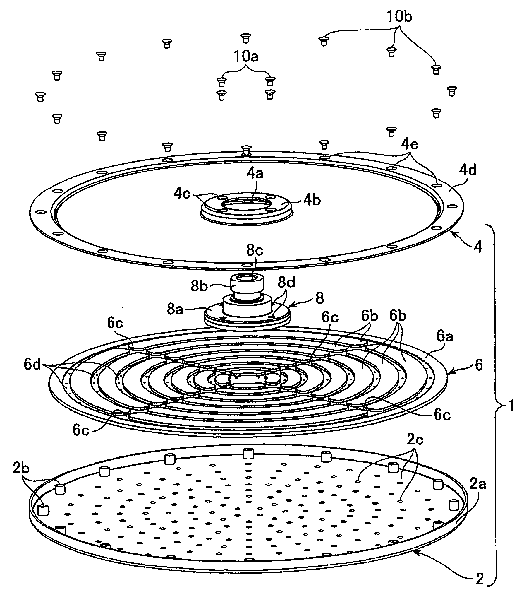
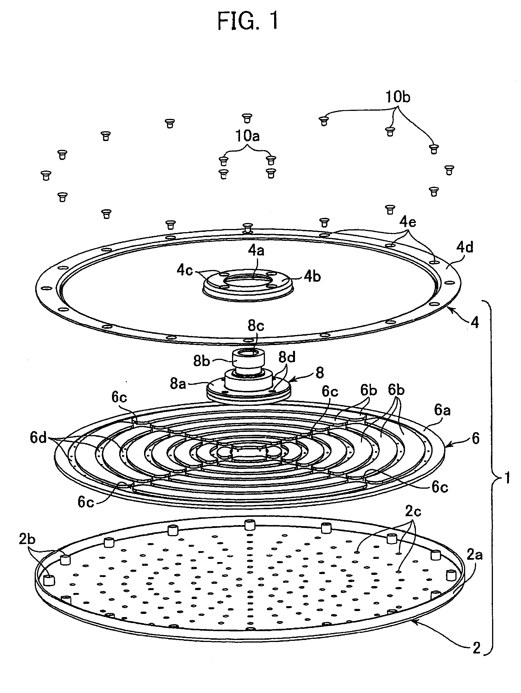
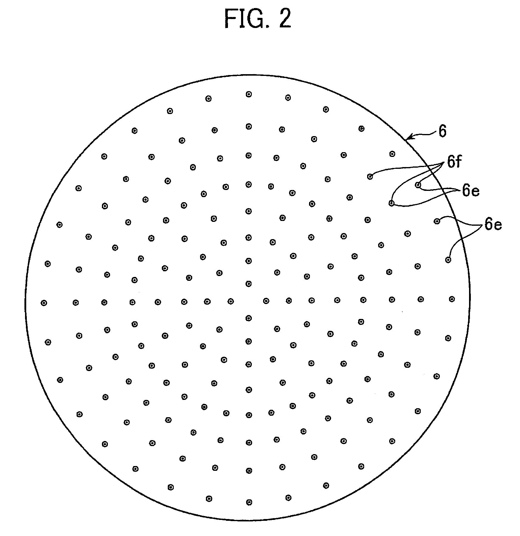
[0047] Firstly, with reference to FIGS. 1 to 3, a showerhead according to the present invention will be described below. FIG. 1 is an exploded perspective view showing the showerhead according to this embodiment. FIG. 2 is a bottom view showing a channel-defining member disposed in the showerhead according to this embodiment, and FIG. 3 is a side view showing the channel-defining member.

[0048] As shown in FIG. 1, the showerhead 1 according to the first embodiment comprises an approximately circular-shaped lower plate 2 serving as a shower plate, an approximately circular-shaped upper plate 4 disposed above the lower plate 2, and an approximately circular disc-shaped channel-defining member 6 disposed between the lower plate 2 and the upper plate 4. The showerhead 1 further includes a joint 8 disposed to extend vertically while penetrating through the upper plate. The showerhead 1 according to this embodiment is intended to allow hot water fed from a pipe (not shown in FIG. 1) connec...

second embodiment

[0092] Further, while the showerhead has been provided with the showerhead body, the watertight member, the shower plate and the back cover, and designed to integrally form the channel walls, the circular wall and others, each of the members or elements may be partly formed integrally or separately according to need. For example, the channel walls and / or the circular wall may be formed separately from the showerhead body, or the channel walls and / or the circular wall may be integrally formed with the watertight member.


PUM


Abstract

Disclosed is a showerhead (1) capable of preventing damages in major or peripheral components and water leakage even if it is increased in size. The showerhead comprises a lower plate (2) formed with a plurality of discharging holes (2c) for discharging shower water therethrough, an upper plate (4) connected to the lower plate and formed with a water inlet port (4c), and a channel-defining member (6) disposed between the lower and upper plates to define an effective channel (6c, 6d) for allowing hot water entered between the lower and upper plates from the water inlet port to be led to each of the discharging holes, and an ineffective channel, so as to reduce a pressure-receiving area of the lower or upper plate to be subjected to a water pressure.

Description

TECHNICAL FIELD [0001] The present invention relates to a showerhead for use as equipment in a bathroom or a shower room. BACKGROUND ART [0002] Heretofore, there has been known a showerhead designed to be mounted to a ceiling or an upper portion of a wall surface of a bathroom or a shower room. The showerhead is provided with a shower plate made of metal or a resin material with high rigidity, and attached to a pipe installed to protrude from a wall surface, so as to discharge shower water from above the head of a user. In this type of conventional showerhead, the shower plate is simply connected to a showerhead body having a water inlet port. Further, the shower plate is convexedly curved in an approximately bowl shape, and formed with a plurality of discharging holes arranged, respectively, along a plurality of lines extending radially from the center of a sphere defined by a curved surface of the shower plate, so as to discharge water therefrom at a spray diameter greater than a ...

Claims


Application Information

Patent Timeline
IPC IPC(8): B05B1/30A62C31/02B05B1/14B05B1/00
CPCB05B1/14B05B1/185
Inventor MIURA, SHOJIYAMAHIGASHI, MASATO
Owner TOTO LTD
Why Eureka
Try Eureka