Method of arthroplastly on a knee joint and apparatus for use in same

a knee joint and arthroplasty technology, applied in the field of knee joint arthroplasty, can solve the problems of increased risk of surgery related complications, increased operation time, and increased discomfort for patients

Inactive Publication Date: 2006-07-27
SMITH & NEPHEW INC
View PDF36 Cites 35 Cited by
  • Summary
  • Abstract
  • Description
  • Claims
  • Application Information

AI Technical Summary

Benefits of technology

[0021] Preferably, the desired spacing of the femur from the tibia will be obtained using at least one spacer inserted into the knee joint between the femur and the tibia to thereby provide the spacing.
[0038] Knowing the relevant dimensions of the chosen tibial and femoral prostheses allows the guide jig to be adapted such that when arranged with the spacer, the guide jig is positioned relative to the tibia and the femur for guiding the cutting of the one or both of them at the depth in the resection of bone therefrom for accommodating the tibial and femoral prostheses. Accordingly, the selected spacer has two roles in unicondylar knee arthroplasty, firstly to space the femur from the tibia and secondly, to act as a reference for resection of bone from one or both of the tibia and the femur to the correct depth.
[0043] Accordingly, in another aspect of the present invention there is provided a method of arthroplasty on a knee joint, comprising the steps of locating a cutter device in position in the knee joint between the tibia and the femur, and moving the tibia through an arc of motion about the femur between backward and forward positions while the cutting device is being operated and is in position between the tibia and the femur, to thereby remove bone substantially to a desired depth from the femur in a direction of travel of the tibia relative to the femur.
[0081] Advantageously, the method of the invention may allow balancing of tension in ligaments and other soft tissue structures of the knee joint to be optimised prior to resection of bone for the fitting of the prostheses. Moreover, ligament and soft tissue release to obtain adequate balancing of tension in the ligaments and soft tissue of the knee joint during flexion and extension of the knee joint as is required for optimum knee joint kinematics prior to or following fitting of trial tibial and femoral implants may be eliminated or reduced.
[0082] In addition, the risk of incorrect alignment and orientation of the tibial and femoral prostheses relative to one another with reference to the action of the ligaments and soft tissue structures may be reduced.
[0083] It is another advantage that as the use of a spacer or spacers as herein described may facilitate both positioning of the guide jig and appropriate tensioning of ligaments and other soft tissue structures of the knee joint, decreased operating times may be provided thereby potentially reducing the incidence of various time related surgical complications such as wound infection, complications associated with the risk of anaesthetic, and thrombosis associated with tourniquet application which can lead to pulmonary embolus and other serious problems. Furthermore, by reducing the need to transect, elevate, or release ligaments and other soft tissue structures of the knee joint, post-operative recovery time may be reduced with consequential reductions in overall health care costs associated with knee arthroplasty.

Problems solved by technology

This leads to an increase in operation time with an associated increase in the risk of surgery related complications.
Moreover, such additional surgical intervention following fitting of the trial implants potentially leads to subsequent increased discomfort for the patient and increased healing times. Methods and apparatus for use in arthroplasty of a knee joint are exemplified in U.S. Pat. No. 5,171,244 and U.S. Pat. No. 5,520,695.

Method used


Image

  • Method of arthroplastly on a knee joint and apparatus for use in same
  • Method of arthroplastly on a knee joint and apparatus for use in same
  • Method of arthroplastly on a knee joint and apparatus for use in same

Examples


Embodiment Construction

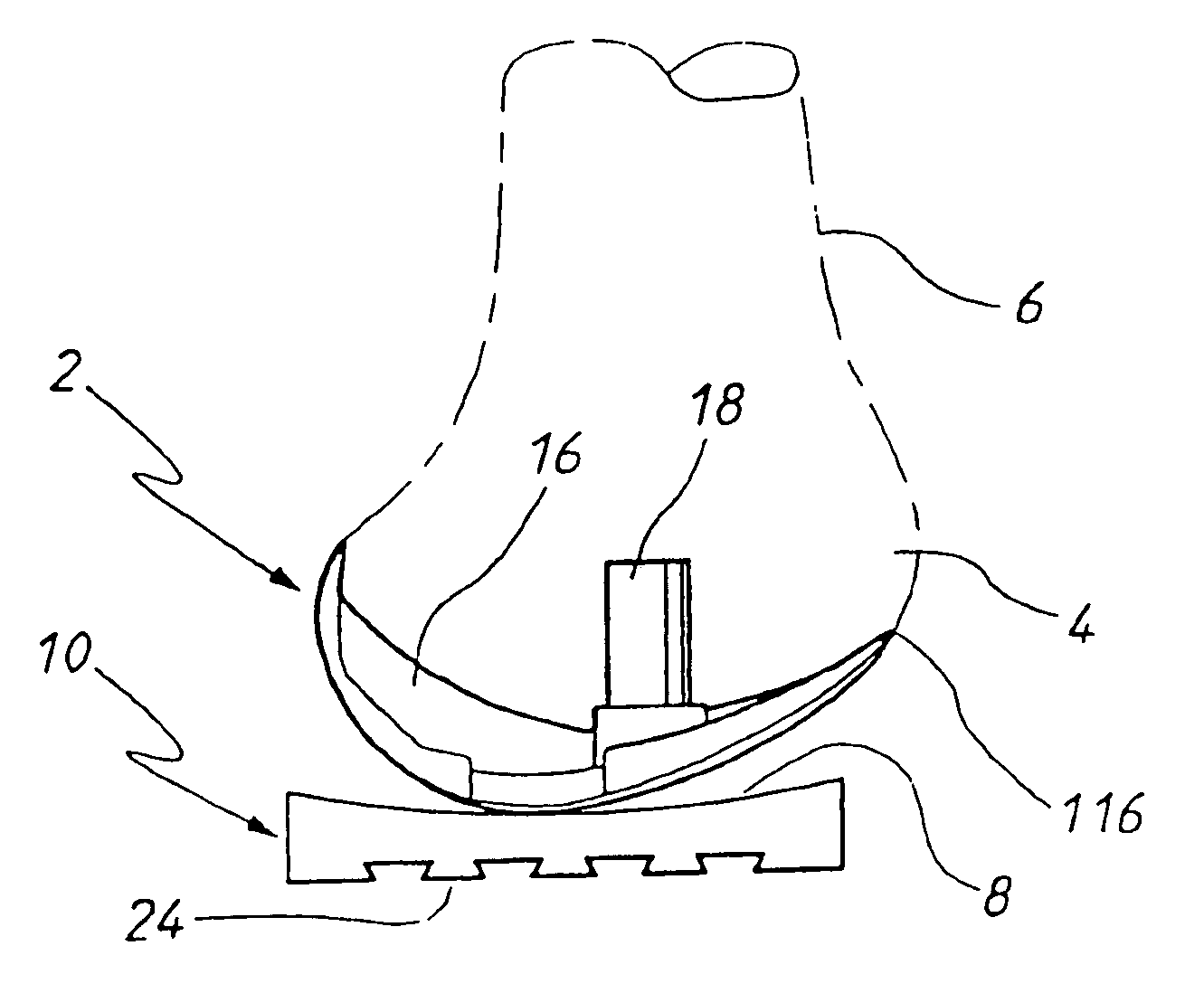
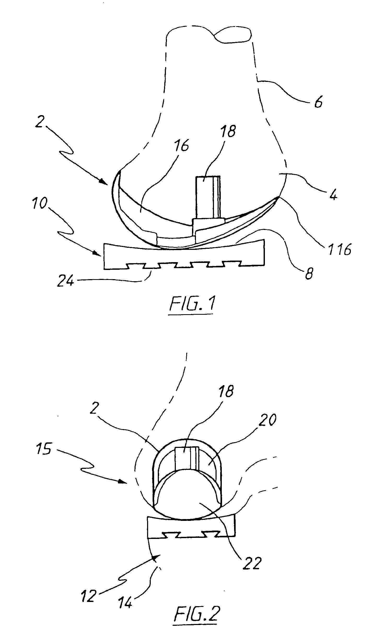
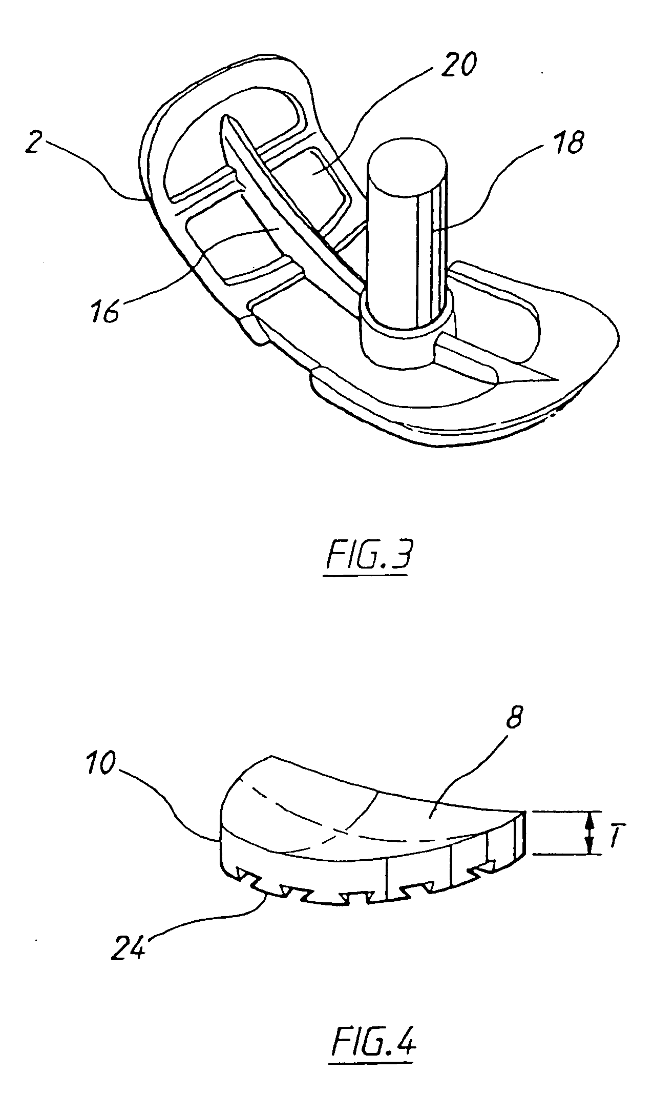
[0126] The femoral prosthesis 2 shown in FIG. 1 is fitted to the medial condyle 4 of the femur 6 and abuts articulating surface 8 of the tibial prosthesis 10 fitted on the corresponding medial condyle 12 of the tibia 14, for articulation thereon as the tibia undergoes flexion and extension about the knee joint 15. The positioning of the femoral prosthesis 2 and the tibial prosthesis 10 is more clearly shown in FIG. 2.

[0127] As shown in FIG. 3, the femoral prosthesis 2 is provided with a centrally orientated upstanding fin 16 incorporating a peg 18 projecting from an interior face 20 of the prosthesis.

[0128] The opposite outer face 22 has a curved contour for facilitating movement of the tibia about the femur. The interior face 20 of the femoral prosthesis is textured to enhance binding of bonding cement used to fix the prosthesis to the femur. The prosthesis itself is formed from a cast cobalt chromium molybdenum alloy conventionally used in the manufacture of such prostheses.

[01...


PUM


Abstract

A method of, and apparatus for, arthroplasty of a knee joint comprising obtaining a desired spacing of the femur from the tibia by inserting a spacer into the knee joint between the femur and the tibia. The spacer is used as a reference for securing a guide jig in position about the knee joint for guiding resection of one or both of the femur and tibia for fitting of tibial and / or femoral prostheses. A method of resecting the femur while moving the tibia through an arc of motion to remove bone to the desired depth, a method of determining the position of the guide jig, the guide jog, an alignment device and the spacer are also described.

Description

CROSS-REFERENCE TO RELATED APPLICATIONS [0001] This application is a continuation of International Application No. PCT / AU01 / 00258 filed on Mar. 9, 2001 and published in English as International Publication Number WO 01 / 66021 A1 on Sep. 13, 2001, which claims priority to Australian Patent Application No. PQ 6161 filed on Mar. 10, 2000, Australian Patent Application No. PQ 8999 filed on Jul. 25, 2000, Australian Patent Application No. PQ 9044 filed on Jul. 27, 2000, and Australian Patent Application No. PQ 9045 filed on Jul. 27, 2000.FIELD OF THE INVENTION [0002] The present invention relates to a method of arthroplasty on a knee joint of a patient. The method extends to both unicondylar knee arthroplasty and knee joint arthroplasty involving resection of both the lateral and medial condyles of the tibia and femur. There is also provided apparatus for use in the method. BACKGROUND OF THE INVENTION [0003] Various methods and apparatus for performing knee arthroplasty and unicondylar kn...

Claims


Application Information

Patent Timeline
Patent Type & Authority Applications(United States)
IPC IPC(8): A61B17/58A61B17/56A61B17/14A61B17/15A61B17/16A61B17/17A61F2/38
CPCA61B17/154A61B17/155A61B17/157A61B17/1659A61B17/1675A61B17/1764A61B2017/1602A61F2002/3895
Inventor PINCZEWSKI, LEO ARIEHPARKER, STEPHEN JOHNMARIK, GREGROCCO, RICHARD A.
Owner SMITH & NEPHEW INC
Why Eureka
Try Eureka