Height adjuctable pedal ring mechanism for bar stool

a pedal ring and height adjustment technology, which is applied in the direction of chairs, stands/trestles, kitchen equipment, etc., can solve the problems of not only requiring strenuous effort in the fastening process, following defects, and endangering the user who is using, so as to achieve stable and safe use, the effect of changing the height of the pedal ring

Active Publication Date: 2006-08-10
HU JUNG HUA
View PDF5 Cites 20 Cited by
  • Summary
  • Abstract
  • Description
  • Claims
  • Application Information

AI Technical Summary

Benefits of technology

[0007] This invention relates to a height adjustable pedal ring mechanism for bar stool, which employs the outer gradient slope of the taper sleeve and the inner gradient slope of the central tube to achieve the goal of changing the height of the pedal ring fast. And this invention is also stable and safe for the user.

Problems solved by technology

This prior art design not only need strenuous effort in the fastening process, but also has the following defects:
It endangers the user who is using it.

Method used


Image

  • Height adjuctable pedal ring mechanism for bar stool
  • Height adjuctable pedal ring mechanism for bar stool
  • Height adjuctable pedal ring mechanism for bar stool

Examples


Embodiment Construction

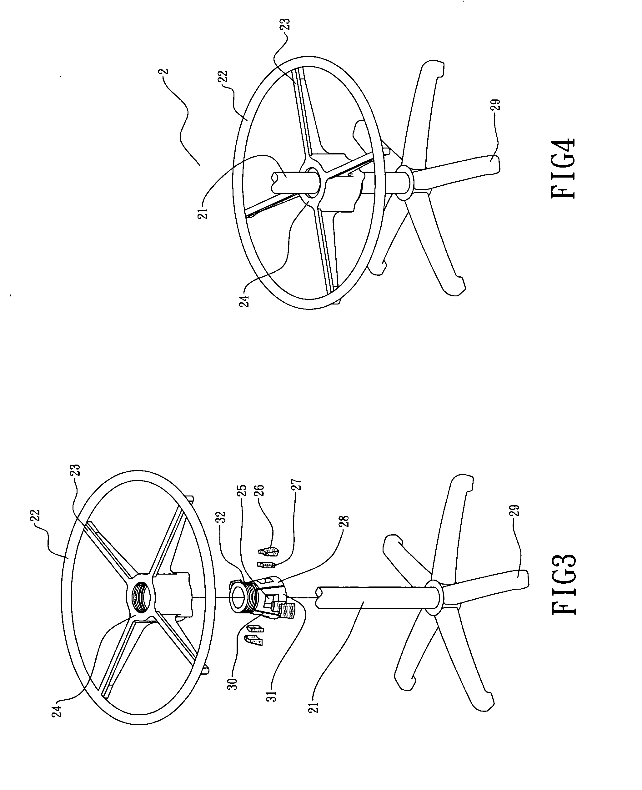
[0016] As shown in FIG. 3, 4, 5, and 6, this invention is a height adjustable bar stool pedal ring mechanism 2, comprising a main shaft 21, a cross-shaped support frame 23 with a central tube 24, a pedal ring 22, a taper sleeve 28, and a base frame 29. The pedal ring 22 is connected to the cross-shaped support frame 23, at the central part of the cross-shaped support frame 23 exists a central tube 24. The central tube 24 has an inner spiral line 32 matching with a spiral line of the taper sleeve 28, and an inner gradient slope 33 matching with an outer gradient slope of the taper sleeve 28.

[0017] A number of slots 30, which are equipped on the lower part of the taper sleeve 28, separate the lower part of the taper sleeve 28 to a number of circular sect plates 31. Each circular sect plate is equipped with a square hole 25, inside the square hole 25 exists a plastic plate 27, which is covered by a ramp plate 26. When the central tube 24 moves downwards by rotation, the inner gradient...


PUM


Abstract

This invention relates to a height adjustable pedal-ring mechanism for bar stool. This mechanism comprises a main shaft, a taper sleeve, a cross-shaped support frame with a central tube, a pedal ring, and a base frame. The pedal ring is connected to the cross-shaped support frame. The taper sleeve has an outer spiral line on the upper part of the taper sleeve and an outer gradient slope on the lower part of the taper sleeve. The cross-shaped support frame is equipped with a central tube at the central part of the cross-shaped support frame. The central tube has an inner spiral line matching with the outer spiral line of the taper sleeve and an inner gradient slope matching with the outer gradient slope of the taper sleeve. This mechanism employs the outer gradient slope of the taper sleeve and the inner gradient slope of the central tube to fix the vertical position of the pedal ring.

Description

BACKGROUND OF THE INVENTION [0001] As shown in FIG. 1 and FIG. 2, the prior art for bar stool pedal ring raising and lowering mechanism 1 employs one-fix-point design, which comprises a main shaft 11, a pedal ring 12, a cross-shaped support frame 13 with a central tube 14, a C-type sleeve 15, a screw 17, and a screw hole 16 on the middle section of the central tube 14. The pedal ring 12 is connected to the cross-shaped support frame. Through the screw hole 16, the screw 17 serves to fasten the vertical position of the pedal ring 12. When the screw 17 rotates onto the main shaft 11, it presses the C-type sleeve 15 onto the main shaft 11. This prior art design not only need strenuous effort in the fastening process, but also has the following defects: [0002] 1. The C-type sleeve 15 is made of plastic material, which has a function to increase the strain force between the screw 17 and the main shaft 11. But when the screw 17 presses the C-type sleeve 15, it damages the surface of the C...

Claims


Application Information

Patent Timeline
Patent Type & Authority Applications(United States)
IPC IPC(8): F16M13/00A47C7/50A47C9/00
CPCA47C7/004A47C7/506A47C9/007A47C7/5064A47C7/5066
Inventor HU, JUNG-HUA
Owner HU JUNG HUA
Why Eureka
Try Eureka