
Surgical staple

Inactive Publication Date: 2006-08-17
TYCO HEALTHCARE GRP LP
View PDF65 Cites 783 Cited by
  • Summary
  • Abstract
  • Description
  • Claims
  • Application Information

AI Technical Summary

Benefits of technology

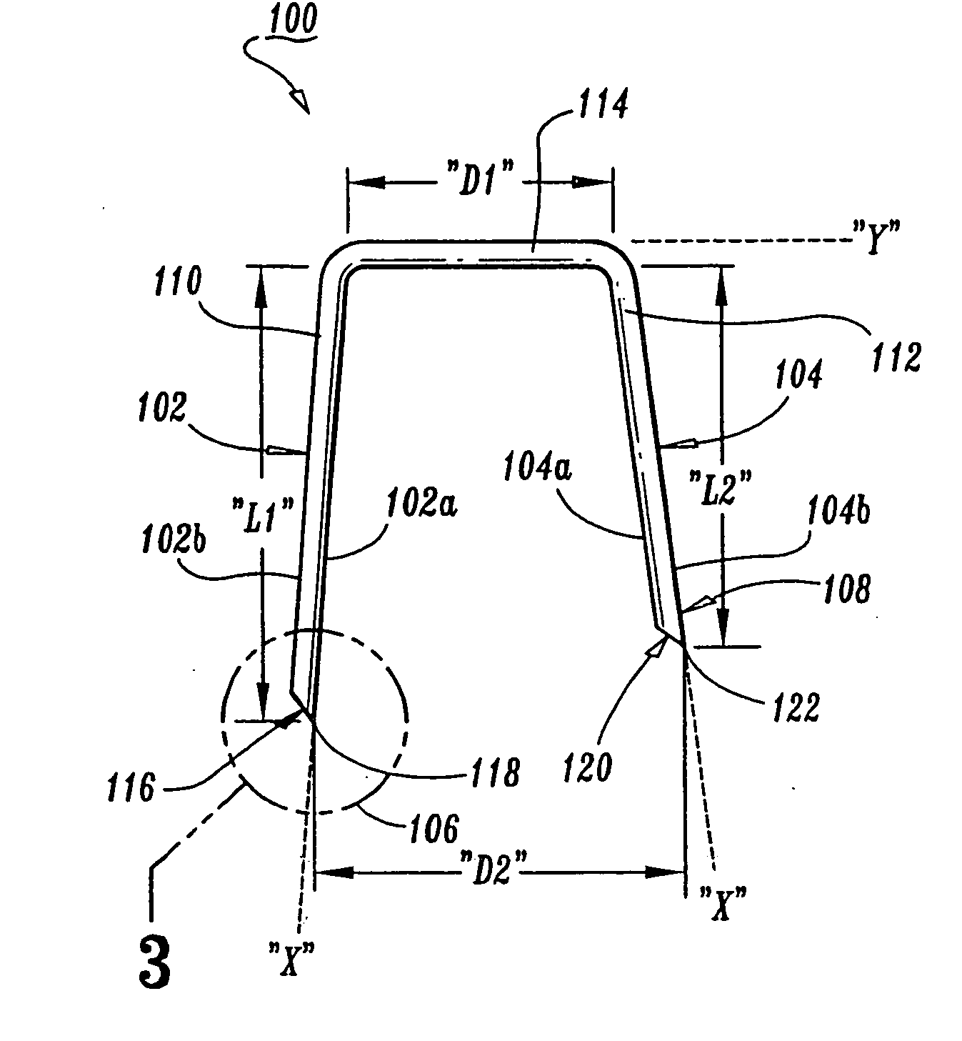
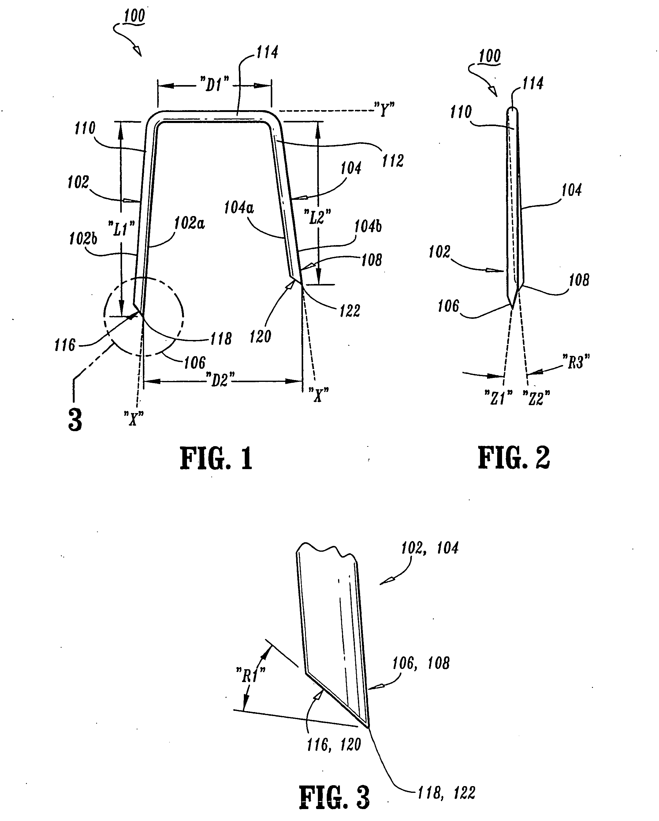
The patent is about a special surgical staple that has two legs and a bridge member that connects them. The first leg has a distal end with a unique angled surface, and the second leg has a shorter length and also has an angled surface. The angle of the surfaces is in the same direction. The staple also has a specific distance between the angled surfaces of the legs. This design allows for improved tissue compression and better wound healing.

Problems solved by technology

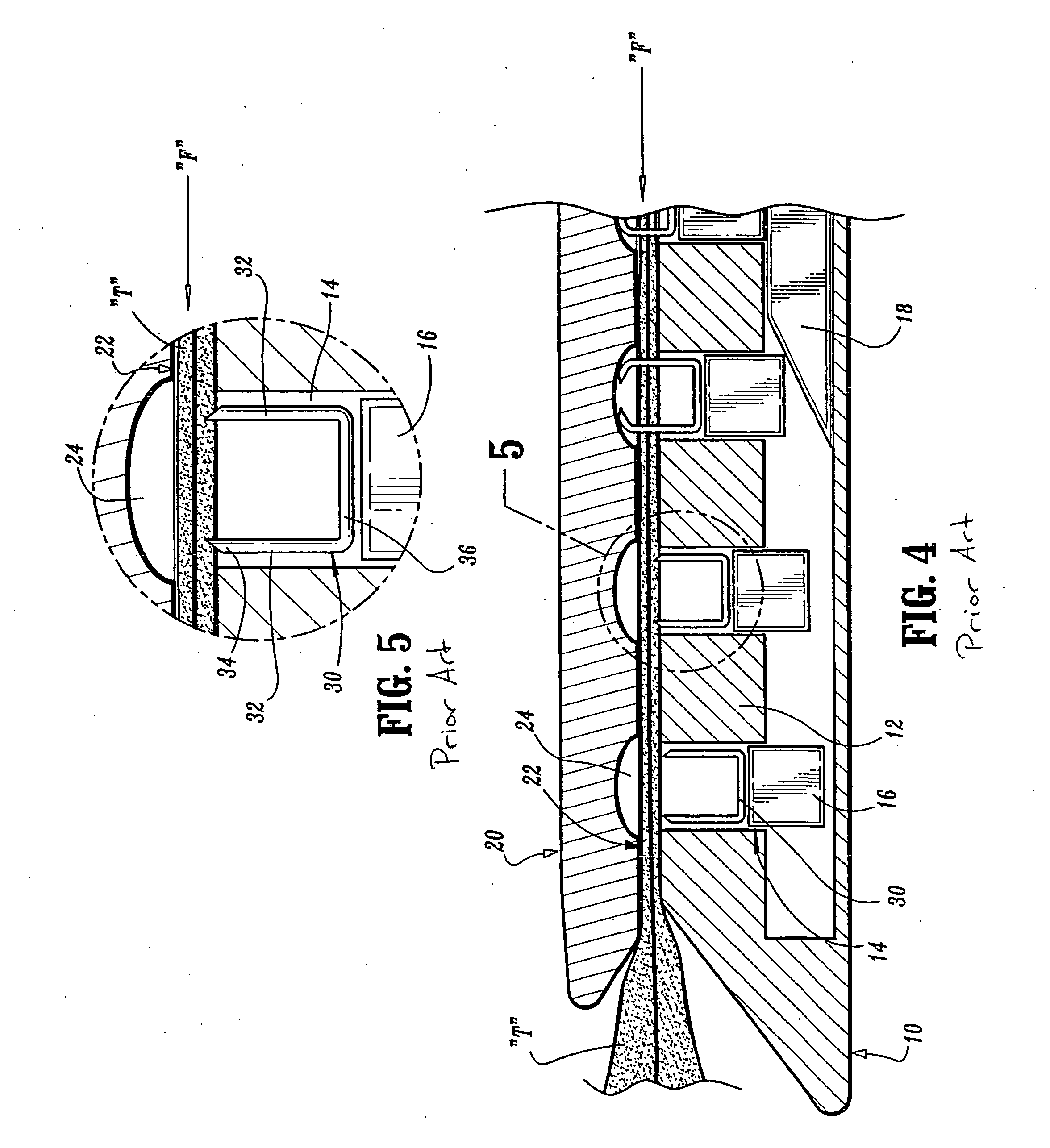
Further, it is evident that the proximal most leg of each staple is unsupported along an inner surface thereof while the distal most leg of each staple is supported along the distal-most surface thereof by the distal wall of each staple pocket.

Method used


Image

  • Surgical staple
  • Surgical staple
  • Surgical staple

Examples


Embodiment Construction

[0026] Preferred embodiments of the presently disclosed surgical stapler will now be described in detail with reference to the drawing figures wherein like reference numerals identify similar or identical elements. In the drawings, and in the description which follows, the term “proximal”, as is traditional, will refer to the end of the device or element which is closest to the operator, while the term “distal” will refer to the end of the device or element which is furthest from the operator.

[0027] It is envisioned that the surgical staples disclosed herein can be used with several known types of surgical staplers for various procedures (examples include: end-to-end anastomosis, “EEA™” circular end-to-end anastomosis, “CEEA™”; gastrointestinal anastomosis, “GIA™”; endoscopic gastrointestinal anastomosis, “Endo GIA™”; and transverse anastomosis, “TA™” staplers available from United States Surgical, a division of Tyco Health-Care Group, LP, Norwalk, Conn.) with each stapler includin...


PUM

PropertyMeasurementUnit
distanceaaaaaaaaaa
distanceaaaaaaaaaa
lengthaaaaaaaaaa

Abstract

A surgical staple is provided which includes a first leg having a distal end portion and a proximal end, a second leg having a distal end portion and a proximal end and a bridge member interconnecting the proximal ends of the first and second legs. In accordance with the present disclosure, the first leg has a first predetermined length and the second leg has a second predetermined length which is less than the first predetermined length of the first leg. The distal end portion of both the first leg and the second leg terminate in a distal angled surface, wherein the distal angled surface of the first leg and the distal angled surface of the second leg are oriented in the same direction as one another. The distal angled surface of the second leg is oriented toward the bridge member.

Description

BACKGROUND [0001] 1. Technical Field [0002] The present disclosure relates to a surgical staple and, more particularly, to a leg configuration for a surgical staple in which the distal tips are oriented in the same direction as one another. [0003] 2. Background of Related Art [0004] Surgical stapling apparatus are widely used in surgical procedures to fasten body tissue in a quick and efficient manner by driving fasteners or staples into the body tissue. In certain types of staplers, a single staple is typically formed against an anvil, e.g., skin staplers, for approximating body tissue. [0005] In other types of staplers, such as those for mechanically stitching together hollow organs, a main linear drive (i.e., a cam member) moves longitudinally in a direction transverse to the direction that the staples are to be driven. Typically, such staplers employ a number of staple drive members or pusher elements which pass through grooved slots of a staple retaining cartridge, such slots b...

Claims


Application Information

Patent Timeline
Patent Type & Authority Applications(United States)
IPC IPC(8): B31B1/00
CPCA61B17/0644
Inventor EMMONS, CLIFFORD L.
Owner TYCO HEALTHCARE GRP LP
Learn More