Laminated filter with improved stop band attenuation

Inactive Publication Date: 2006-08-17
SAMSUNG ELECTRO MECHANICS CO LTD
View PDF6 Cites 5 Cited by
  • Summary
  • Abstract
  • Description
  • Claims
  • Application Information

AI Technical Summary

Benefits of technology

[0021] Therefore, the present invention has been made in view of the above problems, and it is an object of the present invention to provide a laminated filter capable of forming cross capacitive coupling as feeding lines of input lead and / or output lead are coupled to a resonator pattern, and of enhancing an attenuation characteristic of stop band.
[0022] Also, it is another object of the present invention to provide a laminated filter capable of being minimized if feeding lines of the input lead and output lead are aligned in different layers, and easily controlling positions of attenuation poles based on adjustment of the length of feeding line.

Problems solved by technology

Also, since the input and output feeding lines 13a and 13b are formed on the same ceramic sheet, the prior art laminated filter has a drawback in that adjustment of the area and length of the capacitor is restricted.
However, similar to the laminated filter shown in FIG. 1, since the prior art filter disclosed in U.S. Pat. No. 6,437,655 B1 is constructed such that the input and output capacitor patterns form capacitive coupling as the input and output capacitor patterns are coupled to corresponding inductor patterns, respectively, it restricts enhancement in attenuation characteristics.
Also, since the input and output capacitor patterns are formed on the same ceramic sheet, the prior art filter has a drawback in that adjustment of the area and the length of the capacitor is restricted.

Method used


Image

  • Laminated filter with improved stop band attenuation
  • Laminated filter with improved stop band attenuation
  • Laminated filter with improved stop band attenuation

Examples


first embodiment

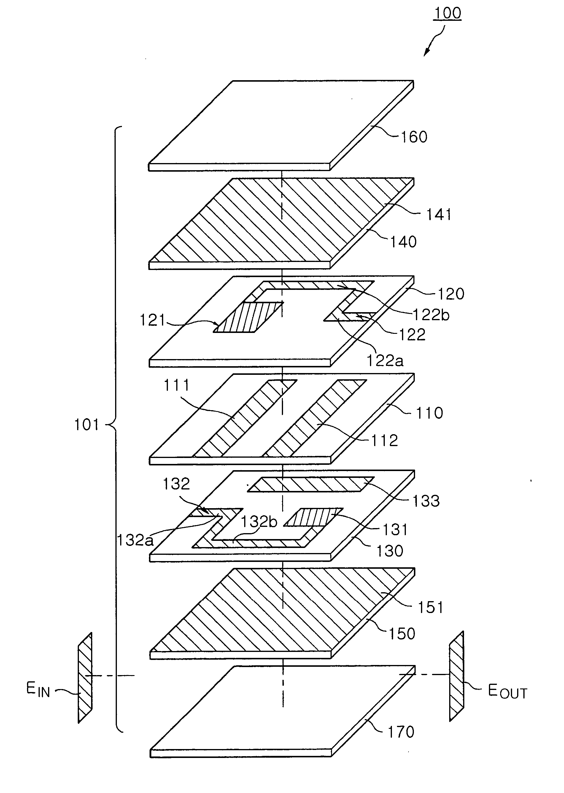
[0039]FIG. 5 is an exploded perspective view according to the present invention.

[0040] With reference to FIG. 5, the laminated filter of the first embodiment of the present invention includes a laminated layer 100, first and second resonator patterns 111 an 112, a first mutual capacitor pattern 121, a first feeding line 122, a second mutual capacitor pattern 131, a second feeding line 132 and a coupling capacitor pattern 133.

[0041] The laminated structure 100 includes a plurality of dielectric layers 101, and input and output electrodes Ein and Eout on the external sides of the plurality of dielectric layers 101.

[0042] The first and second resonator patterns 111 and 112 are placed on a first dielectric layer 110, in which the first and second resonator patterns 111 and 112 are formed in parallel and spaced apart from one another by a predetermined distance. Although the first and second resonator patterns 111 and 112 according to the present invention are implemented as is depicte...

second embodiment

[0075]FIG. 11 is an exploded perspective view of the laminated filter according to the present invention.

[0076] With reference to FIG. 11, the limited filter of the second embodiment of the present invention includes a laminated layer 200, first and second resonator patterns 211 and 212, first and second mutual capacitor patterns 222 and 221, first and second feeding lines 224 and 223, and a coupling capacitor pattern 231.

[0077] The laminated structure 200 includes a plurality of dielectric layers 201, and input and output electrodes Ein and Eout on the external sides of the plurality of dielectric layers 201.

[0078] The first and second resonator patterns 211 and 212 are placed on a first dielectric layer 210, in which the first and second resonator patterns 211 and 212 are formed in parallel and space apart from one another by a predetermined distance. Although the first and second resonator patterns 211 and 212 according to the present invention are implemented according to the ...


PUM


Abstract

Disclosed herein is a laminated filter with improved stop band attenuation, which is adopted in devices using a radio frequency, such as communication systems and / or broadcasting systems. The laminated filter forms cross capacitive coupling as feeding lines of input lead and / or output lead are coupled to a resonator pattern, and enhances an attenuation characteristic of stop band. Also, the laminated filter is minimized if feeding lines of the input lead and output lead are aligned in different layers, and the positions of the attenuation poles are easily controlled by adjusting the feeding line length.

Description

RELATED APPLICATIONS [0001] The present application is based on, and claims priority from, Korean Application Number 2005-12874, filed Feb. 16, 2005, the disclosure of which is incorporated by reference herein in its entirety. BACKGROUND OF THE INVENTION [0002] 1. Field of the Invention [0003] The present invention relates to a laminated filter adopted to devices using a radio frequency (RF), such as communication systems and / or broadcasting systems, and more particularly to a laminated filter capable of forming cross capacitive coupling as feeding lines of input lead and / or output lead are coupled to a resonator pattern, enhancing an attenuation characteristic of stop band, being minimized if feeding lines of the input lead and output lead are aligned in different layers, and easily adjusting a position of attenuation pole based on adjustment of feeding line length. [0004] 2. Description of the Related Art [0005] Generally, a band pass filter passing signals with a specific frequen...

Claims


Application Information

Patent Timeline
IPC IPC(8): H01P1/203
CPCH01P1/20345H01P1/203
Inventor LEE, DONG HWANPARK, SUNG YEOLHONG, KI PYOYOON, HEE SOO
Owner SAMSUNG ELECTRO MECHANICS CO LTD
Why Eureka
Try Eureka