
Rotary drive for a winding shaft of a seat belt retractor

Inactive Publication Date: 2006-08-24
KEY SAFETY SYST
View PDF6 Cites 0 Cited by
  • Summary
  • Abstract
  • Description
  • Claims
  • Application Information

AI Technical Summary

Benefits of technology

[0005] According to the present invention, each drive body comprises at least one engagement part, which during the drive movement engages one of several engagement points located at the periphery of the drive wheel and adapted to the shapes of the en

Problems solved by technology

In this case it is unavoidable that a significant part of the drive energy is lost.

Method used


Image

  • Rotary drive for a winding shaft of a seat belt retractor
  • Rotary drive for a winding shaft of a seat belt retractor
  • Rotary drive for a winding shaft of a seat belt retractor

Examples


Embodiment Construction

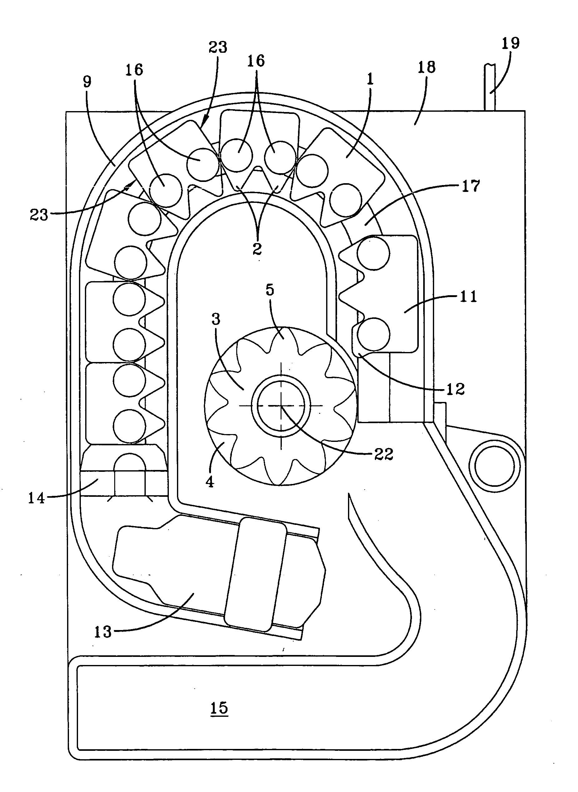
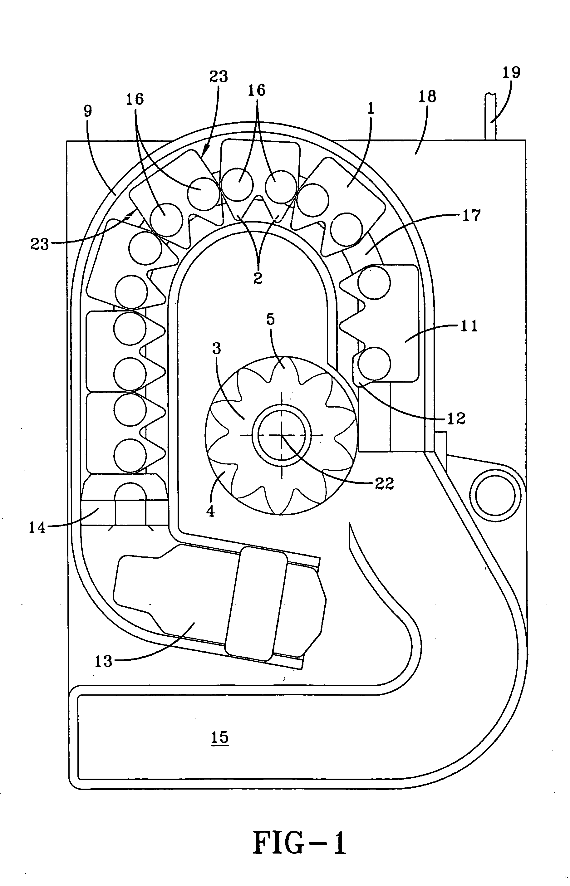
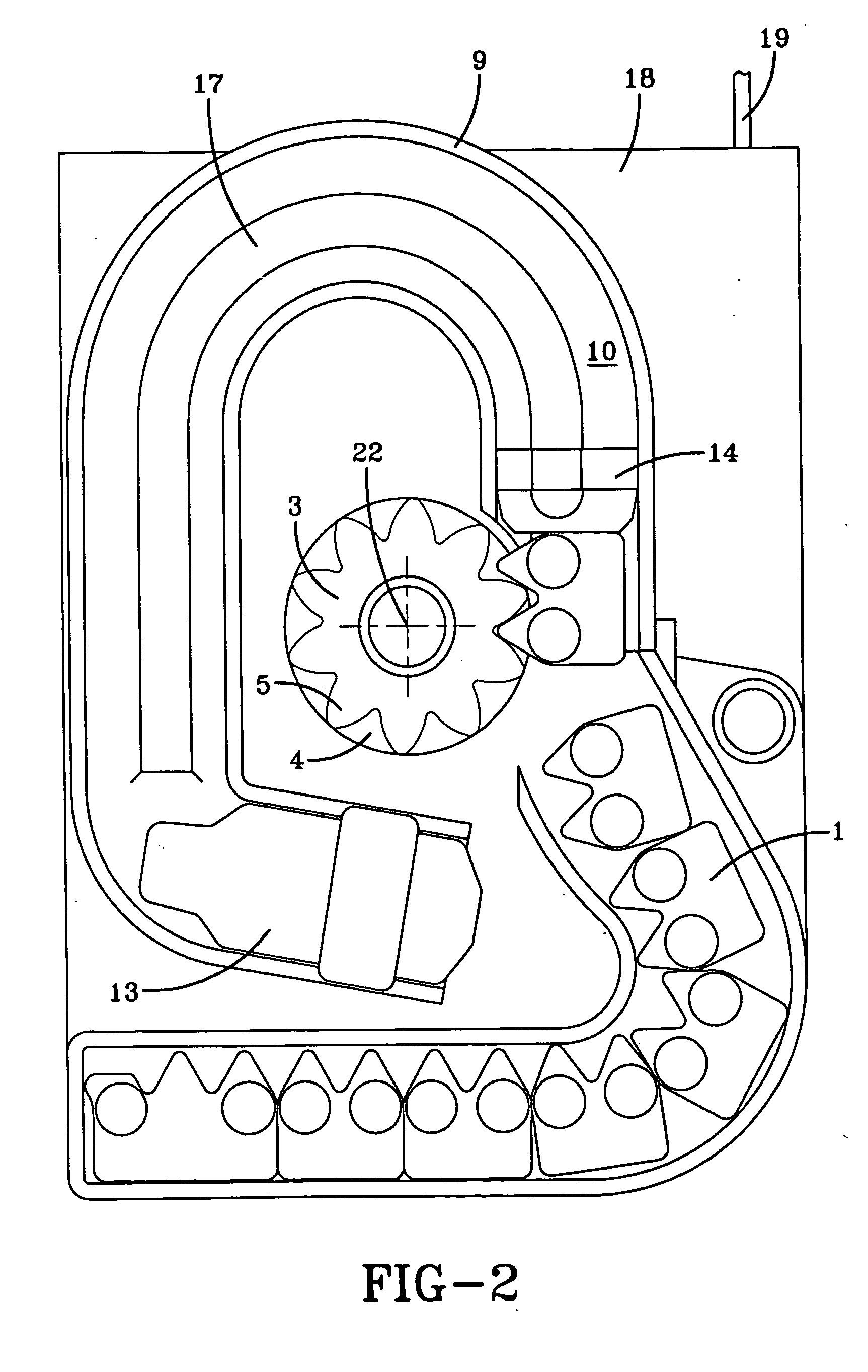
[0019] In the embodiments shown, preformed drive bodies 1 arranged one behind the other are guided in a guide path 10 of a guide device 9. The device is preferably used for power tightening of the vehicle seat belt wound on the winding shaft in the event of a crash. The drive force is preferably used as a thrust force at the end of the arrangement one behind the other of the drive bodies. The thrust force can for instance be supplied by a pyrotechnic drive.

[0020] To achieve a space-saving arrangement, the guide path 10, in which the drive bodies are moved during the drive movement, can display at least one bend. Due to this bend, two parallel straight-lined guide path sections can be connected to one another. The guide path 10 comprises a curved path having a bend portion and two parallel straight path sections. The drive wheel 3 is located in the region of one of the two straight-lined path sections. A drive wheel 3 is connected to a winding shaft of a seat belt retractor 18 for a...


PUM


Abstract

A rotary drive device for a winding shaft of a seat belt retractor has preformed drive bodies arranged one behind the other, which are guided and can be driven in a guide path. Each drive body has engagement parts that can be brought into engagement in an essentially interlocking manner with engagement points located at the periphery of the drive wheel

Description

FIELD OF THE INVENTION [0001] The invention relates to a rotary drive device for a winding shaft of a seat belt retractor for a vehicle seat belt. DISCUSSION OF THE PRIOR ART [0002] U.S. Pat. No. 4,444,010 teaches drive bodies that are arranged one behind the other in a guide means and can be driven along the guide means by a thrust drive. The transmission of the kinetic energy resulting from the drive movement of the drive bodies onto a drive wheel, which is in rotary drive connection with a winding shaft of a seat belt retractor and which rotates around a wheel axis, takes place through frictional contact or in part through an interlocking connection as a result of the ability of the material of the drive bodies to undergo deformation. In this case it is unavoidable that a significant part of the drive energy is lost. [0003] U.S. Pat. No. 5,881,962 teaches a pyrotechnic rotational tightening drive comprising ball-shaped drive bodies, whereby in the region where the drive bodies an...

Claims


Application Information

Patent Timeline
IPC IPC(8): B60R22/46
CPCB60R22/4628B60R2022/4642B60R2022/4647
Inventor SPECHT, MARTIN
Owner KEY SAFETY SYST
Features
  • Generate Ideas
  • Intellectual Property
  • Life Sciences
  • Materials
  • Tech Scout
  • Unparalleled Data Quality
  • Higher Quality Content
  • 60% Fewer Hallucinations
Learn More