Tool mounting device for turning center

a technology of mounting device and turning center, which is applied in the direction of attaching milling device, manufacturing tools, transportation and packaging, etc., can solve the problems of difficult mounting in the turning center, inability to obtain the oil structure, and inability to save energy and resources, so as to reduce the operating cost, and reduce the operating cost

Active Publication Date: 2006-08-24
OM LTD
View PDF20 Cites 4 Cited by
  • Summary
  • Abstract
  • Description
  • Claims
  • Application Information

AI Technical Summary

Benefits of technology

[0011] An object of the present invention is to provide an energy-saving, resource-saving innovative tool mounting device for a turning center that provides a breakthrough from conventional ideas, whereby a tool mounting device can be implemented with a hydraulic cylinder or an air cylinder device with low driving force, and a shared clamp mechanism can be used that allows rotating tools and turning tools to be suitably exchanged, clamped, and fixed even when an ai...

Problems solved by technology

Since a hydraulic cylinder device is therefore necessarily required, an oilless structure cannot be obtained and energy and resources cannot be saved.
On the other the hand, for example, a wedge mechanism (Japanese Laid-open Patent Application No. 2004-202659) developed by the applicant, and other mechanisms cap...

Method used


Image

  • Tool mounting device for turning center
  • Tool mounting device for turning center
  • Tool mounting device for turning center

Examples


examples

[0055] Detailed examples of the present invention are described below with reference to the diagrams.

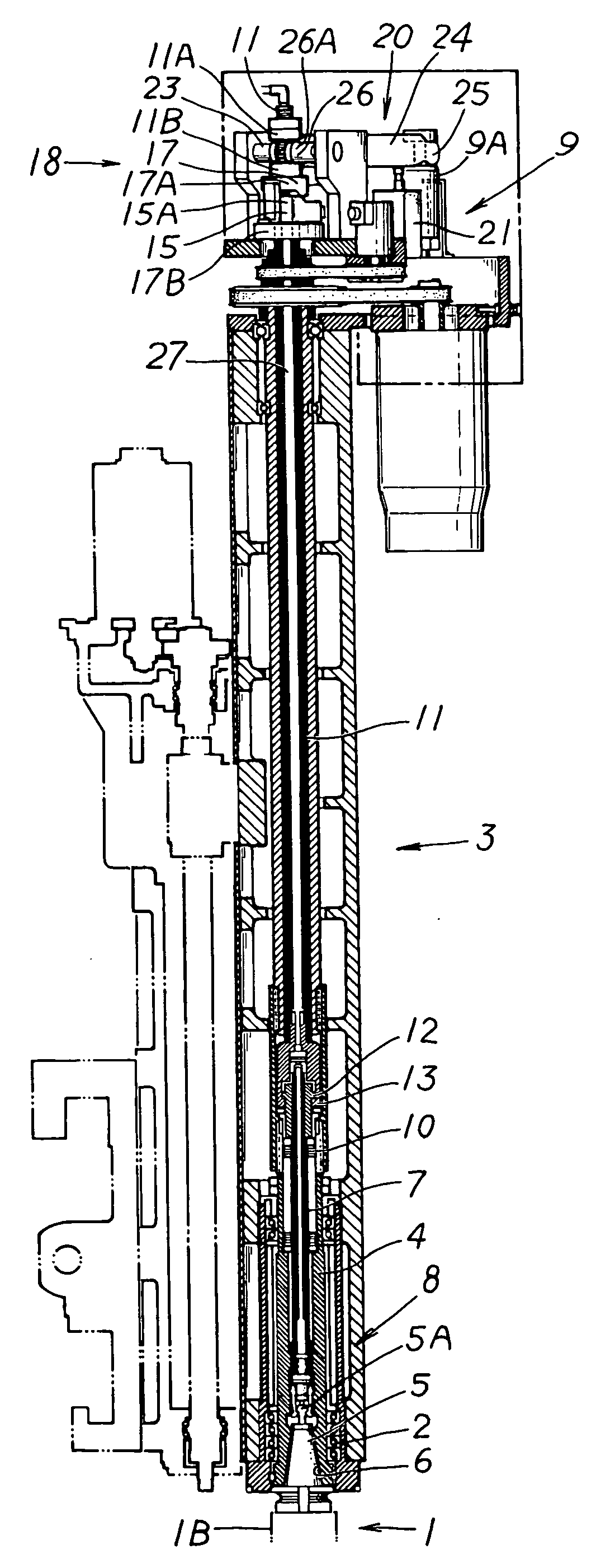
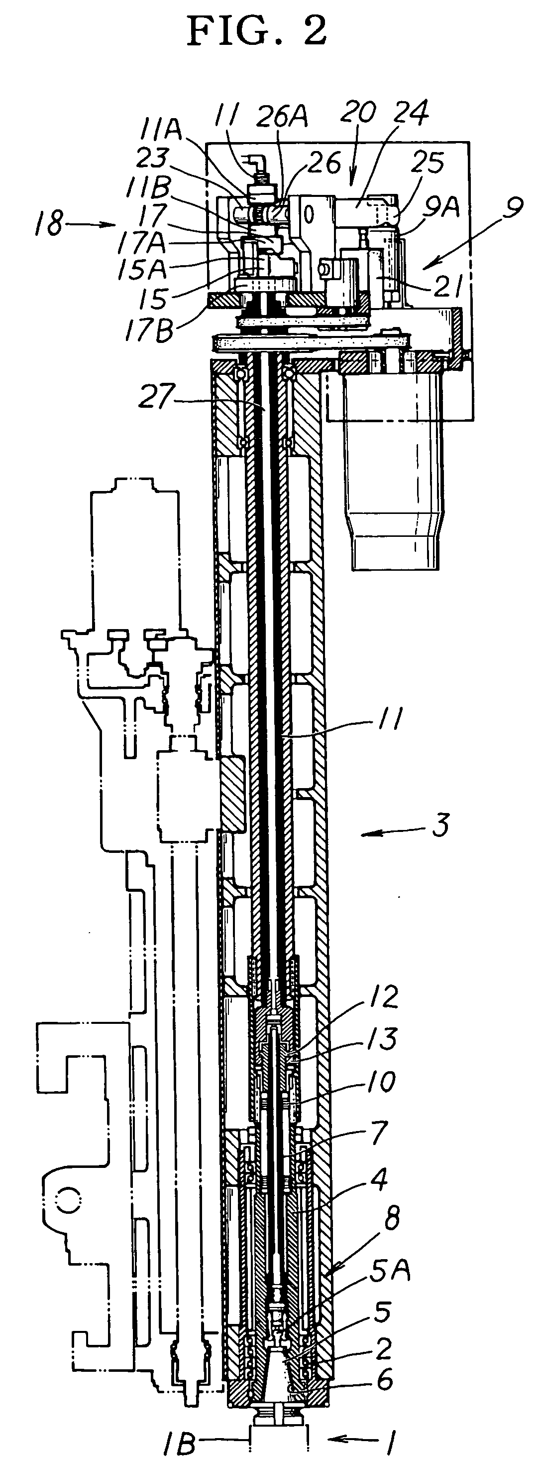
[0056] A mounting engagement unit 6 for engaging a tapered shank 5 mounted on the base end of a tool 1 is provided to a main shaft 4 that is rotatably mounted on a ram 3 via a bearing unit 2. A clamp mechanism 8 is provided for clamping a clamping convexity 5A of the tapered shank 5 when a drawbar 7 is retracted, and drawing / engaging the tapered shank 5 to the mounting engagement unit 6 to mount / fix the tool 1 on the main shaft 4 so as to allow the shank to be clamped and released based on the reciprocating control of the drawbar 7. In the present example, clamping is actuated by a configuration in which an elastic member 10 is fitted to the drawbar 7 and is used as a compression-resisting elastic unit for pushing the drawbar 7 upward against the main shaft 4 during compression. The drawbar 7 is retracted using the retracting force of the elastic member 10. Clamping is released by a...


PUM

PropertyMeasurementUnit
Currentaaaaaaaaaa
Digital informationaaaaaaaaaa
Distanceaaaaaaaaaa

Abstract

To provide a tool mounting device for a turning center that allows a rotating tool to be clamped/fixed using a shared clamp mechanism (8), and a turning tool (1B) to be clamped/fixed in an engaged/locked state in a turning center. In the turning center configured with the shared clamp mechanism (8), a cylinder device (9) acting as a drawbar drive device (9) of the clamp mechanism (8) has a first clamp position (b) and second clamp position (c) in relation to a release position (a); a rotation allowance gap (14) is maintained between the stopper (12) and the bearing unit (13) in the first clamp position (b) to specifically clamp/fix the rotating tool (1A); the reciprocating driver (11) is driven by an amount equal to the rotation allowance gap (14) in the second clamp position (c); and when the bearing unit (13) and the stopper (12) are brought into contact and a load is imposed, the stopper (12) is supported/stopped by the bearing unit (13), and the reciprocating driver (11) is engaged/locked by the wedge mechanism (18) in the position of the return blocking state in which the return of the drawbar (7) is blocked.

Description

BACKGROUND OF THE INVENTION [0001] 1. Field of the Invention [0002] The present invention relates to a tool mounting device for a turning center that can suitably exchange rotating tools and turning tools to perform milling and cutting (turning). [0003] 2. Background Art [0004] In a turning center, a mounting engagement unit for engaging a tapered shank provided to the base end of a tool is disposed on a main shaft that is rotatably mounted on a ram via a bearing unit. A clamp mechanism is disposed for clamping a clamping convexity of the tapered shank by retracting the drawbar, and drawing / engaging the tapered shank to the mounting engagement unit to detachably / replaceably mount and fix a tool to the main shaft, so as to allow the shaft to be clamped and released based on the reciprocating control of the drawbar. Tools are suitably attached and detached using the shared clamping mechanism, and rotating tools are rotatably clamped / fixed together with the main shaft. When turning too...

Claims


Application Information

Patent Timeline
IPC IPC(8): B23C5/26
CPCB23B31/261Y10T409/309464Y10T408/953Y10T409/309408Y10T408/95Y10T82/2511
Inventor NAKAMURA, TAKIOGOTO, AKIHIROSHIMIZU, TATSUOUEDA, TAKASHI
Owner OM LTD
Why Eureka
Try Eureka