Implant for intervertebral space

a technology for intervertebral space and implants, applied in the field of implants for intervertebral space, can solve the problems of contact surfaces, difficult rotation of implants in both directions,

Active Publication Date: 2006-08-31
SYNTHES USA +1
View PDF8 Cites 27 Cited by
  • Summary
  • Abstract
  • Description
  • Claims
  • Application Information

AI Technical Summary

Benefits of technology

[0005] The present invention is to provide a remedy for the above-discussed disadvantages. It is an object of the invention to produce an implant for an inter

Problems solved by technology

A disadvantage of the Beckers implant is that the contact surfaces can have a structure, with ribs extending either parallel to the longit

Method used


Image

  • Implant for intervertebral space
  • Implant for intervertebral space
  • Implant for intervertebral space

Examples


Embodiment Construction

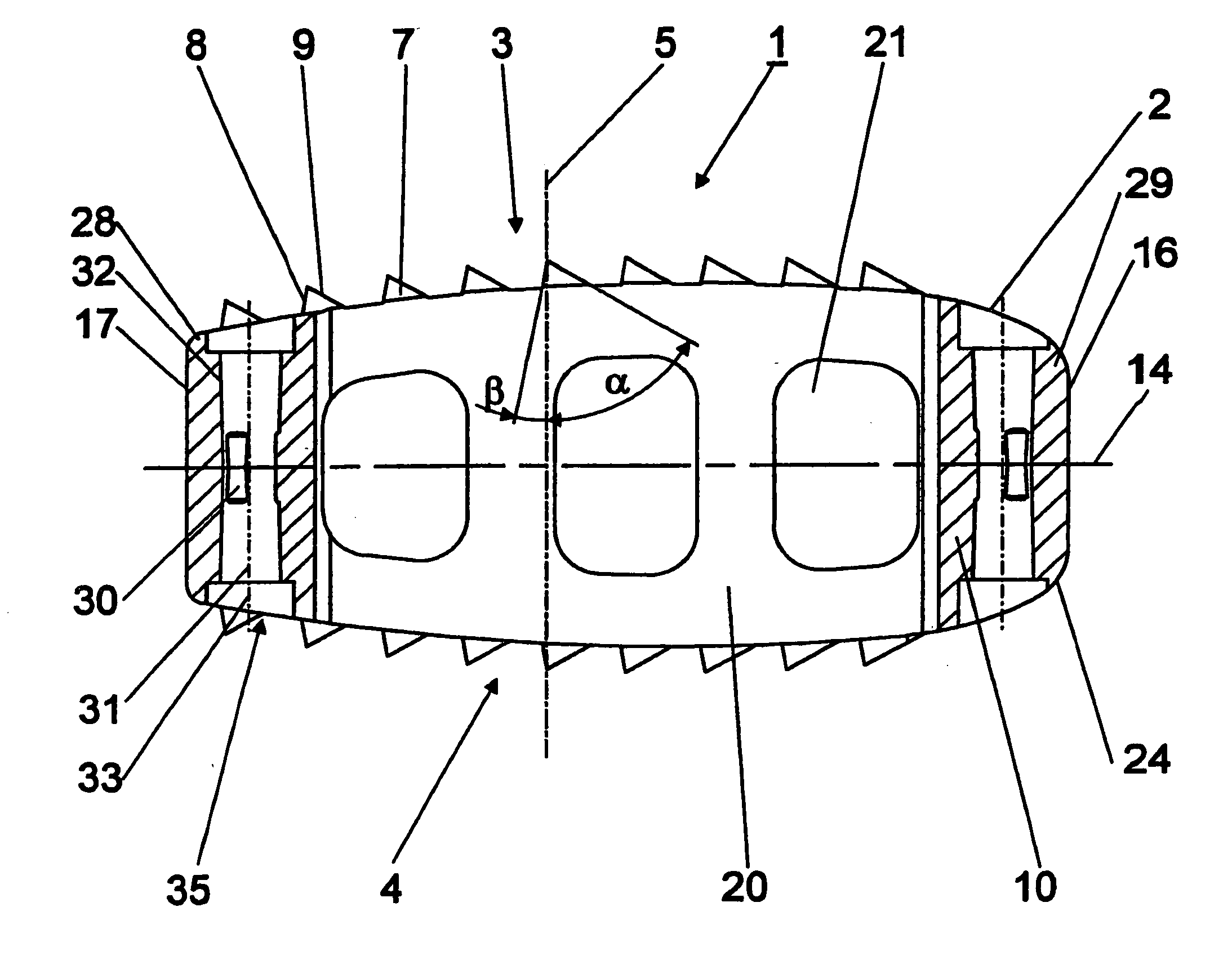
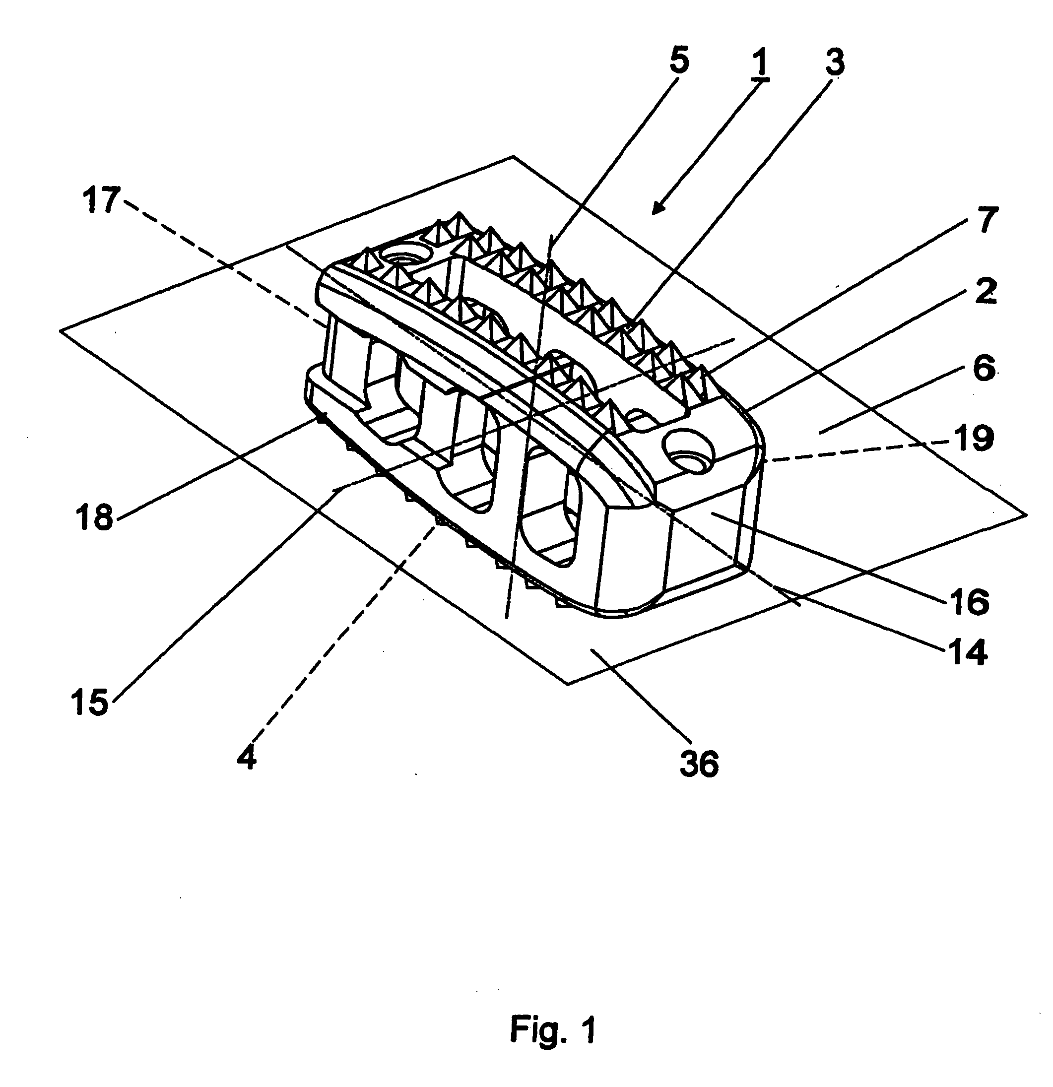
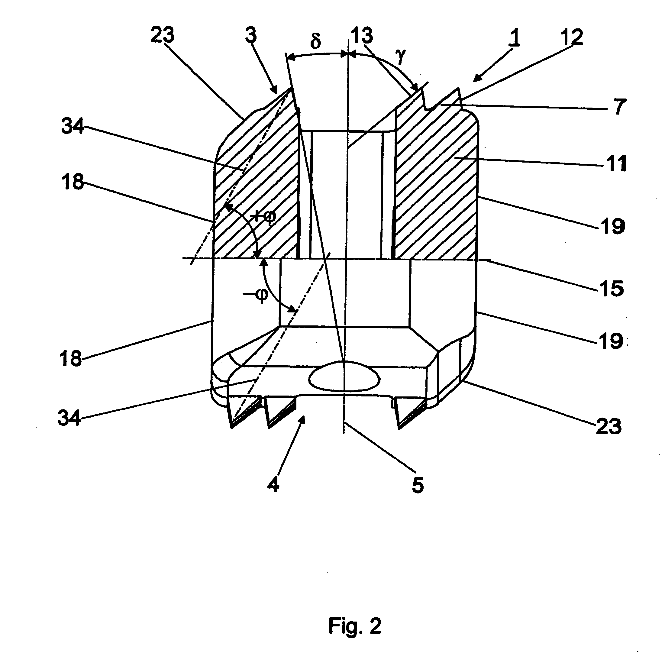
[0042] The implant 1, shown in FIGS. 1 to 3, consists of an essentially cuboid-shaped body 2 with top and bottom convex contact surfaces 3, 4 to be placed on the superior and inferior surface, respectively, of the two adjoining bodies of the vertebra and a central axis 5 intersecting the contact surfaces 3, 4. Two lateral surfaces 18, 19 are arranged at right angles to the contact surfaces 3, 4, as well as a front lateral surface 16 and a rear lateral surface 17. Longitudinal axis 14, which is perpendicular to the central axis 5, intersects both the front lateral surface 16 and the rear lateral surface 17. A transverse axis 15, which is also perpendicular to the central axis 5 of the body 2, intersects lateral surfaces 18, 19. The longitudinal axis 14, as well as the transverse axis 15, define a central plane 6 situated between the contact surfaces 3, 4; this plane being perpendicular to the central axis 15. The distance between the two lateral surfaces 18, 19 is smaller than the di...


PUM


Abstract

An implant for an intervertebral space with a shaped body. The implant has a top contact surface to be placed on a base plate of a body of the vertebra adjoining the implant from above, a bottom contact surface to be placed on a cover plate of a body of the vertebra adjoining the implant from below, two lateral surfaces, a front lateral and a rear lateral surface as well as a central axis that intersects the two contact surfaces, a longitudinal axis that intersects the front and rear lateral surfaces and a transverse axis that intersects the lateral surfaces. The implant also has a central plane situated between the contact surfaces and at right angles to the central axis of the body. The contact surfaces have a plurality of macroscopic teeth with central axes, where the central axes of the plurality of teeth are inclined relative to the central plane in such a manner, that a rotation of the body of 90° about the longitudinal axis is facilitated in one direction and impeded in the other direction. The distance between the two lateral surfaces is smaller than the distance between the two contact surfaces.

Description

CROSS REFERENCE TO RELATED APPLICATION [0001] This application is a continuation of International Patent Application No. PCT / CH2003 / 000412, filed Jun. 24, 2003, the entire contents of which is expressly incorporated herein by reference.TECHNICAL FIELD [0002] The present invention relates generally to implants for intervertebral spaces. BACKGROUND OF THE INVENTION [0003] It is well known in the art to use intervertebral implants in a posterior lumbar fusion of two adjoining bodies of the vertebra. WO 95 / 08306 to Beckers describes such an implant for an intervertebral space. The Beckers implant comprises a body with a flat lens-shaped profile having convex surfaces. The convex surfaces are positioned on the superior and inferior, respectively, surfaces of the adjoining bodies of the vertebra, so that the greatest part of the profile of the implant coincides with the biconcave shape of the sagittal interface of the intervertebral space. In the other two planes, the body has parallel fl...

Claims


Application Information

Patent Timeline
IPC IPC(8): A61F2/44A61B17/02A61F2/00A61F2/30A61F2/46
CPCA61B2017/0256A61F2/447A61F2/4611A61F2002/3008A61F2002/30774A61F2002/30777A61F2002/30785A61F2002/30789A61F2002/30841A61F2002/30904A61F2002/4475A61F2002/4629A61F2250/0098A61F2310/00017A61F2310/00023A61F2310/00131A61F2310/00155A61F2002/30593
Inventor LECHMANN, BEATFRIGG, ROBERTBURKE, ROGER
Owner SYNTHES USA
Why Eureka
Try Eureka