Dust shutter for an optical adapter

a technology of optical adapters and dust shutters, which is applied in the direction of optical light guides, instruments, optics, etc., can solve the problems of preventing the connector and the device from functioning properly, affecting the performance of the optical adapter, and being susceptible to dust or debris

Active Publication Date: 2006-09-14
YAZAKI CORP
View PDF7 Cites 116 Cited by
  • Summary
  • Abstract
  • Description
  • Claims
  • Application Information

AI Technical Summary

Problems solved by technology

When the optical connectors are not latched to the optical adapter, cavities in the optical adapter, which are provided for coupling the optical connector, are susceptible to dust or debris.
This can affect the performance of the optical connection between the mating connectors, and even prevent the connector and the device from functioning properly.
Moreover, the light of a laser beam typically used for optical transmission in high-power applications can damage the eyes of an individual that installs or repairs the optical fiber connection.
However, the removable plug can be easily misplaced.
Insertion and removal of the plug may also require considerable manual dexterity on the part of the individual that installs or repairs the optical fiber connection.
It is also not possible to configure a removable plug that automatically closes the opening upon removal of the optical connector, should such automatic closing be desired.
However, this covering lid does not form a tight seal to prevent the ingress of dust.
In addition, the covering lid is made of multiple pieces, which increases the cost and reduces the reliability of the dust shutter.
Accordingly, U.S. Pat. No. 6,247,849's dust shutter would not properly seal the holes on a typical adapter because the top and bottom of the dust shutter casing includes openings that form the anchoring tabs.
This can be inconvenient to individuals engaged in connector installation because the covering lid must be manually retained in the open position during connector insertion.

Method used


Image

  • Dust shutter for an optical adapter
  • Dust shutter for an optical adapter
  • Dust shutter for an optical adapter

Examples


Embodiment Construction

[0026] While the invention is open to various modifications and alternative forms, specific embodiments thereof are shown by way of examples in the drawings and are described herein in detail. There is no intent to limit the invention to the particular forms disclosed.

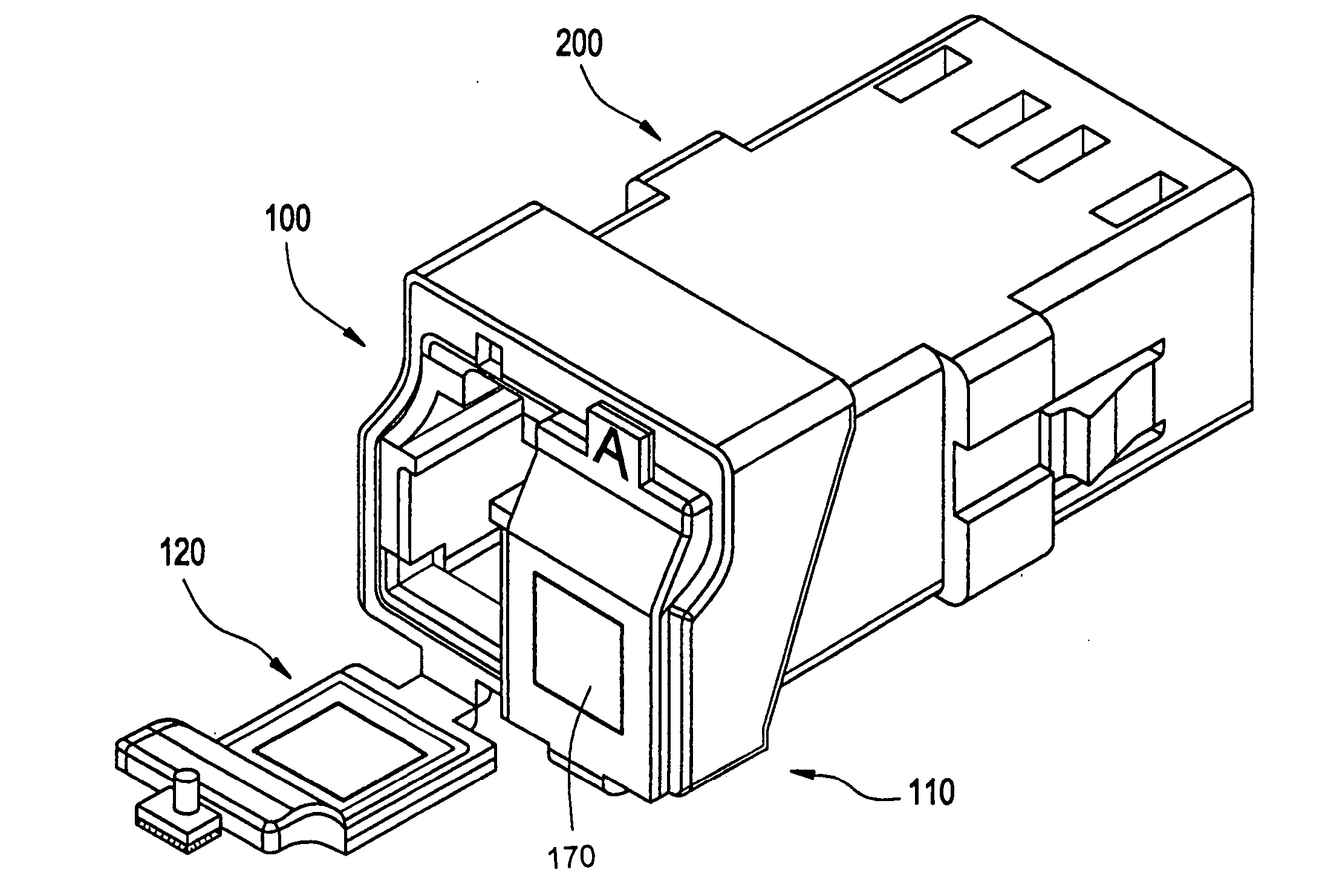
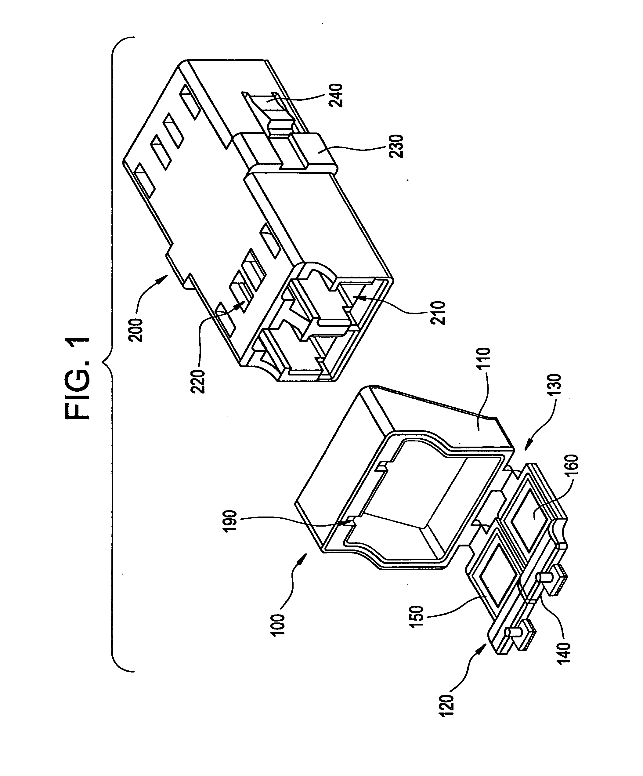
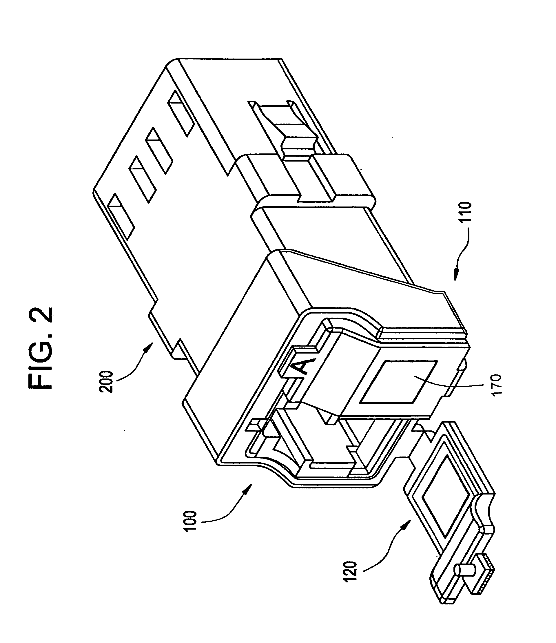
[0027] A first exemplary embodiment of the invention is shown in FIGS. 1-6b. FIGS. 1 and 2 are perspective views of a dust shutter 100 and an optical adapter 200. FIGS. 3 and 4 are side and front views, respectively, of the dust shutter 100 and the optical adapter 200. FIGS. 5a-6b show details of the cover 120 and a latch 140 of the dust shutter 100.

[0028] As shown in FIGS. 1 and 2, the dust shutter 100 includes a collar 110 and one or more covers 120. Hinges 130 connect the covers 120 to the collar 110 and allow the covers 120 to be provided in either an open position or a closed position with respect to the collar 110, as shown with respect to covers 120 of FIG. 2.

[0029] When each cover 120 is in the open position...


PUM


Abstract

A dust shutter for an optical adapter, includes a collar, wherein the collar is capable of being provided around an end of the optical adapter; a cover; a hinge that connects the cover to the collar; the hinge configured such that the cover can be provided in an open position and a closed position with respect to the collar; and a latch provided on the cover that attaches the cover to the collar in the closed position; wherein the collar, the cover, the hinge, and the latch form a unitary structure.

Description

FIELD OF THE INVENTION [0001] The present invention relates to a dust shutter for an optical adapter. BACKGROUND [0002] Optical adapters provide a connection between optical fibers of an optical fiber communication system. Two optical connectors, which are provided at ends of two optical fiber cables, are latched to the optical adapter, in order to provide a coupling between the ends of the optical fibers within the optical fiber cables. Each adapter has at least one set of opposing ports to accept the connectors on the optical fiber cables. This allows the light passing through one of the optical fiber cables to be transmitted through the other optical fiber cable. The optical adapter is formed by back-to-back receptacles, each receptacle configured to accept the optical fiber cable. The receptacle could also be a device receptacle where the optical fiber cable connector is mated to the front side of the receptacle and a device can be positioned on the backside of the receptacle. V...

Claims


Application Information

Patent Timeline
Patent Type & Authority Applications(United States)
IPC IPC(8): G02B6/00
CPCG02B6/3825G02B6/3849
Inventor LAMPERT, NORMAN ROGERLEWIS, WAYNE LLOYD
Owner YAZAKI CORP
Why Eureka
Try Eureka