Position detection device

Active Publication Date: 2006-09-21
IEE INT ELECTRONICS & ENG SA
View PDF6 Cites 29 Cited by
  • Summary
  • Abstract
  • Description
  • Claims
  • Application Information

AI Technical Summary

Benefits of technology

[0017] By alternating the measurements in the two opposing directions, it is thus easily possible to detect the position where a force is acting in the plane defined by the two directions of the ohmic resistors and therefore to determine the X-Y coordinates of a point of action of a force. Henceforth it is therefore possible to determine the coordinates X and Y of the point of action of a force using a position detector that now requires only 4 terminals so as to connect it to an associated measurement circuit. It follows that the connection of the position detector is considerably simplified.
[0018] In addition, all the electrical terminals of the detector needed to connect it are located on a single substrate, which considerably facilitates the connection of the detector, especially to a printed circuit. This is because it is consequently possible to use standard crimping connectors to ensure reliable contact between the position detector and an assoc

Problems solved by technology

This fact creates problems, especially when connectin

Method used


Image

  • Position detection device
  • Position detection device
  • Position detection device

Examples


Example

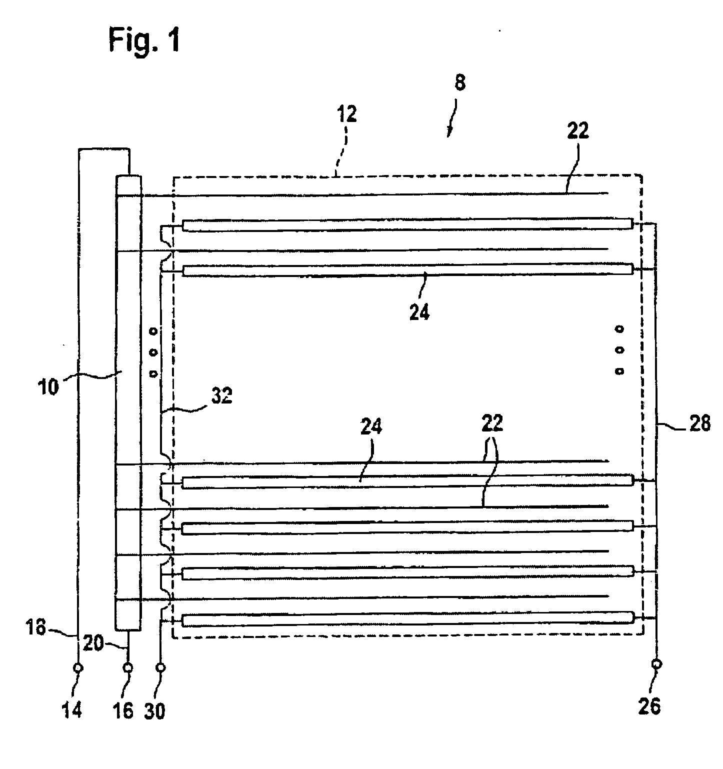
[0031]FIG. 1 shows a view of the arrangement of the conductors on the first substrate of a position detector 8. A linear ohmic resistor 10, which extends along an active surface 12 of the position detector, is placed on a substrate. In the embodiment shown, the active surface has a generally square shape. However, it should be noted that other shapes are possible, for example oval, circular, rectangular, etc.

[0032] The ohmic resistor 10 is connected between a first terminal 14 and a second terminal 16 of said position detection device via conducting lines 18, 20.

[0033] A plurality of electrical conductors 22 are connected to the first ohmic resistor 10 at discrete points thereon, the electrical conductors 22 extending from the first ohmic resistor toward the interior of the active surface 12. In the embodiment shown, the conductors 22 are distributed equidistantly and extend parallel to one another. It goes without saying that a different arrangement of conductors is possible.

[00...


PUM


Abstract

A position detection device including a substrate; a first ohmic resistor applied to the substrate and extending along an active surface of the position detector, whereby the first ohmic resistor is connected between a first terminal and a second terminal of the position detection device; a plurality of electric conductors connected to the first ohmic resistor at places that are distinct therefrom, the electric conductors extending from the first ohmic resistor inside the active surface alternating between the first electric conductors, whereby one first end of the conductor elements is connected to a third terminal of the position detection device. The conductor elements are configured as ohmic resistors extending through the active surface of the device and a second end of the conductor elements is connected to a fourth terminal of the position detection device.

Description

INTRODUCTION [0001] The present invention relates in general to a device for detecting a position where a force acts and, where appropriate, the intensity of this force. [0002] It is known to construct devices for detecting a position where a force acts on the basis of sheet switches. A sheet switch comprises two support sheets, which are held a certain distance apart using a spacer. The spacer includes at least one recess that defines an active region of the switch, in which the two support sheets face each other. Inside this active region, at least two electrodes are arranged on the support sheets in such a way that an electrical contact is established between the electrodes when the two support sheets are pressed together through the effect of a force acting on the switch. [0003] Depending on the application, a layer of semiconductor material may be placed between the electrodes, in such a way that the switch exhibits pressure-sensitive behavior, that is to say its resistance var...

Claims


Application Information

Patent Timeline
IPC IPC(8): G09G5/00G06F3/033G06F3/041G06F3/045
CPCG06F3/0414G06F3/045G06F3/04144
Inventor SERBAN, BOGDAN
Owner IEE INT ELECTRONICS & ENG SA
Why Eureka
Try Eureka