Gimbal

Active Publication Date: 2017-09-14
YUNEEC TECH CO LTD
View PDF13 Cites 11 Cited by
  • Summary
  • Abstract
  • Description
  • Claims
  • Application Information

AI Technical Summary

Benefits of technology

The present invention is a gimbal with a Wi-Fi circuit board that allows for independent transmission of video signals. The gimbal includes a housing with a gyroscope board, camera, and camera main control board, along with Wi-Fi antennas. The Wi-Fi circuit board is connected to the camera main control board and the camera. The circuit board rotates with the housing to save wires and avoid wear and tear. The gimbal also includes a heat sink to dissipate heat, sealed housing with end caps to prevent component erosion, and multiple shock absorption balls to reduce vibration and ensure image quality. The technical effects of this invention are simplified connections, reduced failure rates due to wear and tear, and improved image quality.

Problems solved by technology

However,the gimbal itself now on the market does not include a Wi-Fi (wireless fidelity) digital transmission system, and it is necessary for the gimbal to transmit through an external device.
Moreover, the internal structure of the gimbal is complex, electronic components need to be connected with each other through wires, which results in the complex connections among the overall wires, thus it is prone to failure.
In addition, because the camera itself rotates, the wires will be driven to move together, thus it is easy to failure due to worn wires.

Method used


Image

  • Gimbal
  • Gimbal
  • Gimbal

Examples


Embodiment Construction

[0029]The present invention is further more clearly and completely explained with accompanying preferred embodiments and drawings as follows.

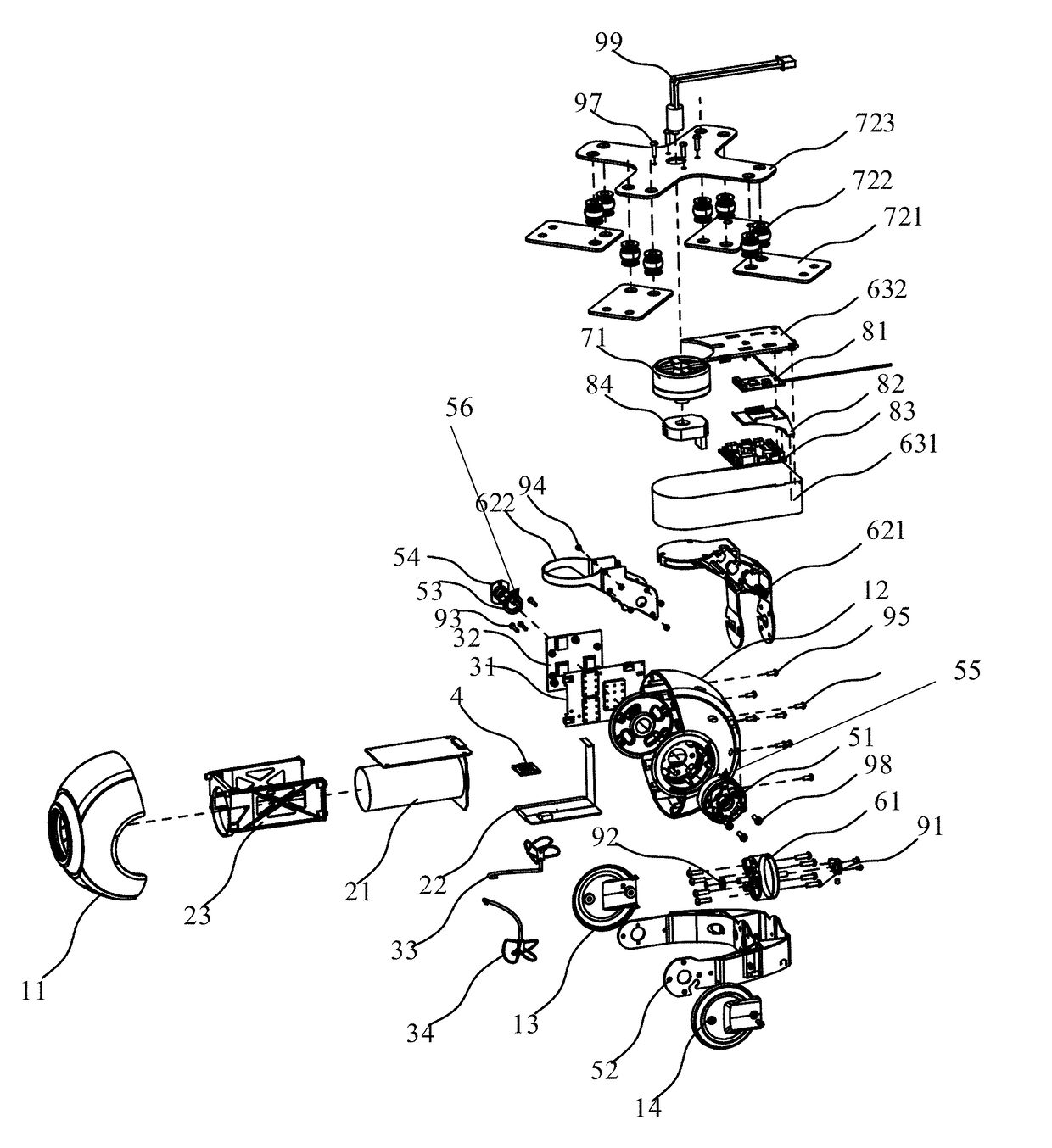
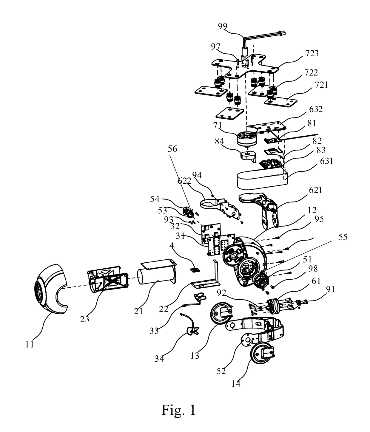
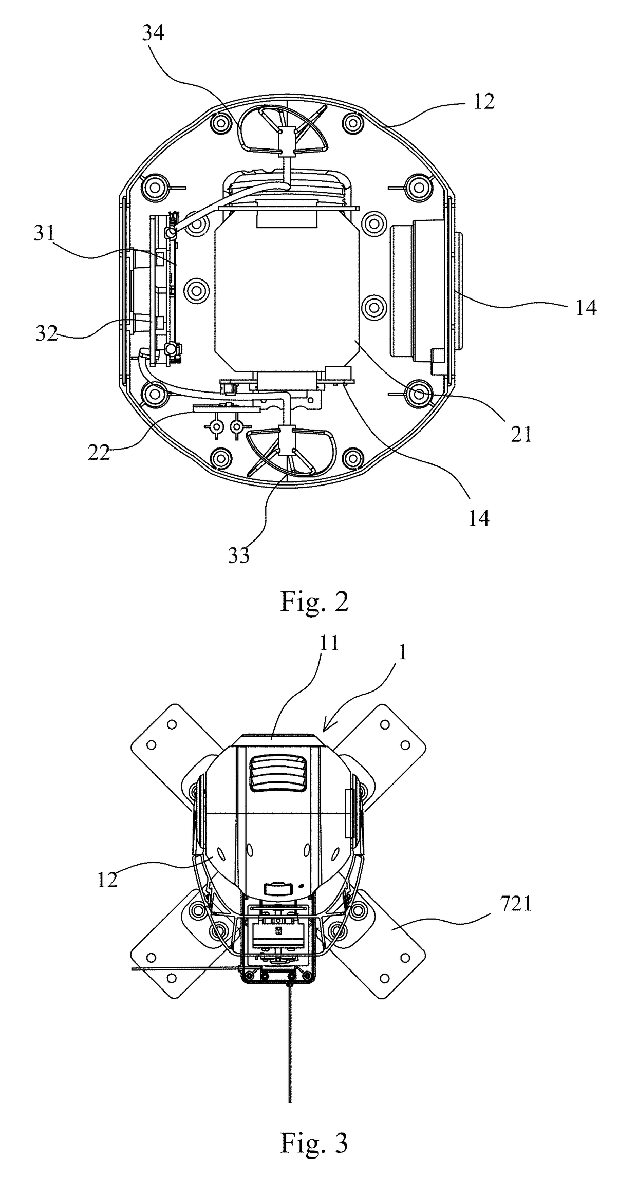
[0030]As shown in FIGS. 1-5, the present invention provides a gimbal. Specifically, referring to FIGS. 3-5, the gimbal comprises a housing 1 which is capable of rotating around three axes.

[0031]Referring to FIGS. 1 and 2, the housing 1 comprises a front cover 11 and a rear cover 12 connected with the front cover 11 through multiple screws 95.

[0032]A gyroscope board 4, a camera 21 and a camera main control board 22 electrically connected with the camera 21 are disposed in the housing 1. The camera 21 is installed on the camera frame 23. The camera frame 23 is connected with the rear cover 12 through multiple screws 96 for fastening.

[0033]A Wi-Fi (wireless fidelity) circuit board 31, Wi-Fi antennas 33, 34 and a heat sink 32 are also disposed in the housing 1, wherein:the Wi-Fi circuit board 31 is electrically connected with the camera main contro...


PUM


Abstract

A gimbal includes a housing (1). A gyroscope board (4), a camera (21), and a camera main control board (22) electrically connected with the camera are disposed in the housing. A Wi-Fi circuit board (31) and a Wi-Fi antenna (33) are also disposed in the housing. The Wi-Fi circuit board is electrically connected with the camera main control board. The camera is fixed on the housing. The gimbal achieves the independent Wi-Fi transmission, so that the structure is simplified.

Description

CROSS REFERENCE OF RELATED APPLICATION[0001]This is a U.S. National Stage under 35 U.S.C. 371 of the International Application PCT / CN2015 / 097351, filed Dec. 15, 2015, which claims priority under 35 U.S.C. 119(a-d) to CN201420795952.2, filed Dec. 15, 2014. The full text of the above-mentioned Chinese patent application is included in the present invention.BACKGROUND OF THE PRESENT INVENTION[0002]Field of Invention[0003]The present invention relates to a gimbal.[0004]Description of Related Arts[0005]With the development of society and industry by leaps and bounds, the UAV (Unmanned Aerial Vehicle) aerial photography has been applied to more and more fields, such as film and television shooting, fire patrol shooting and traffic monitoring. The synchronous transmission of the UAV aerial photography has important significances. However,the gimbal itself now on the market does not include a Wi-Fi (wireless fidelity) digital transmission system, and it is necessary for the gimbal to transm...

Claims


Application Information

Patent Timeline
IPC IPC(8): H04N5/225H05K7/14H05K1/02H05K5/03B64D47/08H05K5/00
CPCH04N5/2252B64D47/08H05K5/0004H05K1/0203H05K5/03H05K7/1427H04B7/04B64C2201/127H05K2201/066H05K2201/10098G03B17/561H04W84/12B64C39/024H04N23/51B64U2101/30
Inventor TIAN, YUJIANG, WENYAN
Owner YUNEEC TECH CO LTD
Why Eureka
Try Eureka