Emergency room triage system

a triage system and emergency room technology, applied in the field of emergency room triage system, can solve the problems of unreliable detection of ami from a standard 12-lead ecg, high risk of ami in coronary atherosclerosis, and so as to reduce the time to treatment, increase the battery life of implants, and display and print quickly

a triage system and emergency room technology, applied in the field of emergency room triage system, can solve the problems of unreliable detection of ami from a standard 12-lead ecg, high risk of ami in coronary atherosclerosis, and so as to reduce the time to treatment, increase the battery life of implants, and display and print quickly

US20060212085A1Inactive Publication Date: 2006-09-21ANGEL MEDICAL SYST

Image

  • Emergency room triage system
  • Emergency room triage system
  • Emergency room triage system

Examples


Embodiment Construction

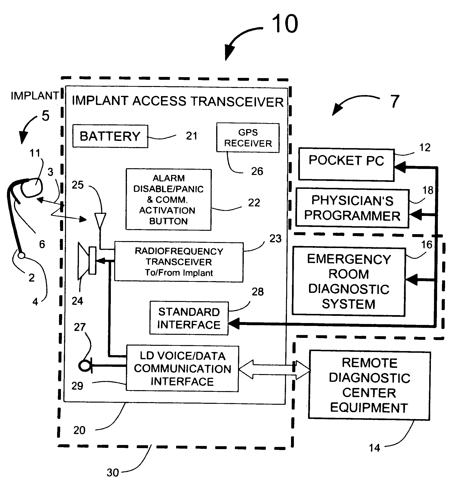
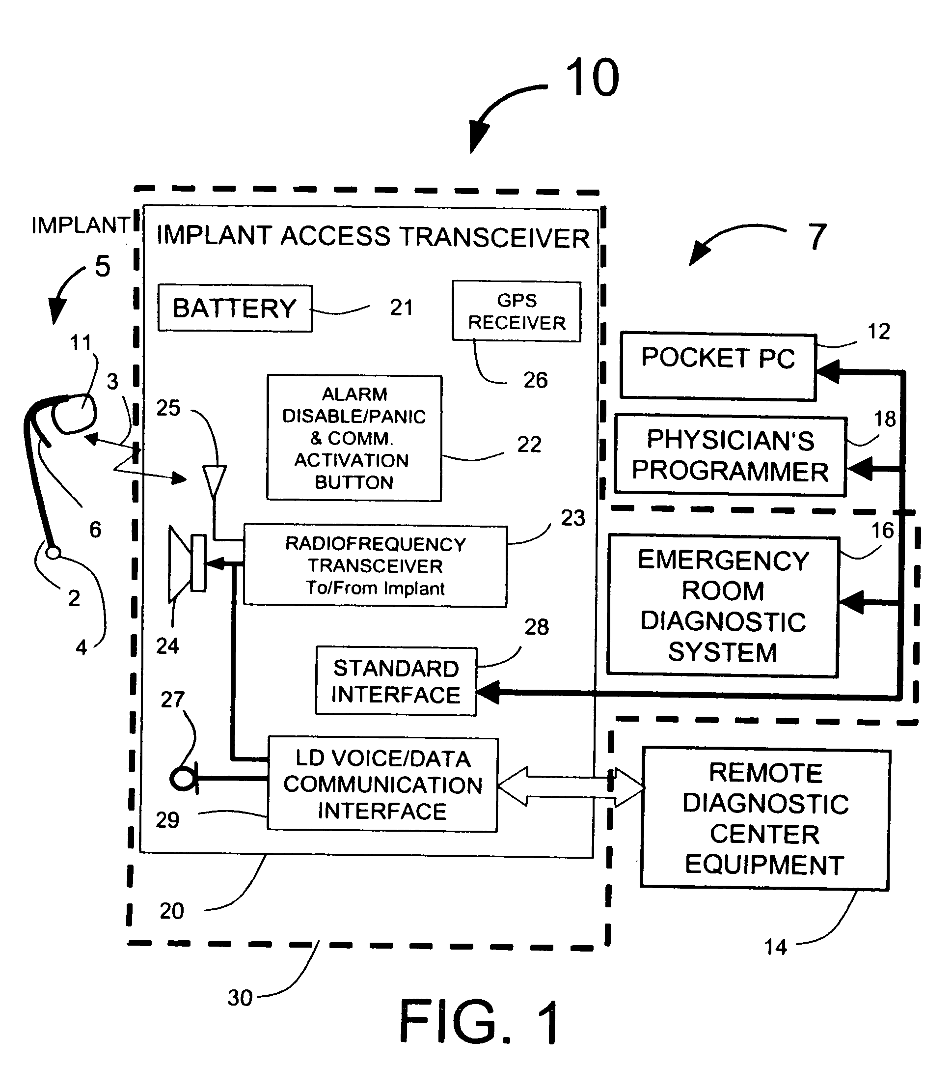
[0044]FIG. 1 illustrates one embodiment of the Guardian system 10 consisting of an implanted cardiosaver system 5 and external equipment 7. The cardiosaver system 5 includes a cardiosaver 11, an antenna 6 and an electrode 4 that is part of a lead 2. The cardiosaver 11 includes electronic circuitry that can detect a cardiac event such as an acute myocardial infarction or arrhythmia and can warn the patient with an internal alarm signal when the event occurs. The cardiosaver 11 can store the patient's electrogram for later readout and can send and receive wireless signals 3 to and from the external equipment 7 via the antennas 6 and 25. The wireless signals would typically use the FCC medical band (Medical Implant Communications Service) and can be implemented using a radiofrequency system such as the CC 1000 chipset from CHIPCOM as described by Fischell et al in U.S. patent application Ser. No. 10 / 994,466 which is incorporated herein by reference. The functioning of the cardiosaver s...


PUM


Abstract

A patient diagnostic emergency room triage system includes an implanted cardiac device which may be a cardiosaver, pacemaker or cardiac defibrillator for recording electrogram data associated with the detection of a cardiac event. A communication mechanism receives electrogram data from the implanted cardiac device and a visual display displays the electrogram data recorded by the implanted cardiac device. The visual display permits displaying electrogram data associated with an ST segment related cardiac event.

Description

CROSS REFERENCE TO RELATED APPLICATION [0001] This application is a Continuation-in-Part application of U.S. patent application Ser. No. 10 / 844,411, titled “Emergency Room Triage System,” filed May 13, 2004, now pending.FIELD OF USE [0002] This invention is in the field of systems, including devices with diagnostic capabilities implanted within a human patient. BACKGROUND OF THE INVENTION [0003] Heart disease is the leading cause of death in the United States. A heart attack (also known as an acute myocardial infarction (AMI)) typically results from a thrombus (i.e., a blood clot) that obstructs blood flow in one or more coronary arteries. AMI is a common and life-threatening complication of coronary heart disease. Myocardial ischemia is caused by an insufficiency of oxygen to the heart muscle. Ischemia is typically provoked by physical activity or other causes of increased heart rate when one or more of the coronary arteries are narrowed by atherosclerosis. Patients will often (but...

Claims


Application Information

Patent Timeline
21 Sep 2006
Publication
US20060212085A1
IPC
A61N1/37; A61B5/00; A61B5/0402; A61B5/0452; A61N1/362; A61N1/372
CPC
A61B5/0031; A61B5/0452; A61B5/1112; A61B5/411; A61N1/37247; A61B5/686; A61B2505/01; A61B5/00
Inventors
FISCHELL, DAVID R.; HARWOOD, JONATHAN